Links from this page
Useful Links
The on-line book, “The Contact Patch” has a chapter on “The Roadbed” with a simple description of the track and its sub-structure.
Rail expansion and contraction under changing temperatures is an article in Rail Engineer magazine.
Here is a comparison table for ballasted and slab track.
A chapter “Track Alignment” in the on-line book The Contact Patch describes the basic geometry.
Another useful chapter in “The Contact Patch” is on “Turnouts”
Introduction
The infrastructure of a railway is a complex and multi-disciplinary engineering system involving earthworks, bridges, tunnels, steelwork, timber, and track system to form the base upon which the railway runs. To give a train a good ride, the track alignment must be set to within a millimetre of the design. Many different systems exist throughout the world and there are many variations in their performance and maintenance.
This page looks at the basics of infrastructure and track design and construction with drawings, photos and examples from around the world. Some railway management systems include signalling, stations and electric power supply systems as part of the infrastructure too. These are dealt with in separate pages on this site.
Background
The track is a fundamental part of the railway infrastructure and represents the primary distinction between this form of land transportation and all others in that it provides a fixed guidance system. The track is the steering base for the train and has evolved from an ancient design of vehicle guidance with origins dating, some historians have suggested, from the Sumerian culture of 2000 BC. The modern railway version is based on a steel wheel running on a steel rail. Other forms of guided vehicle technology exist; rubber-tyred trains, magnetic levitation and guided busways, for example, but these are not dealt with here. There is a good description of the French-based rubber tyred train technology available at The Rubber Tyred Metro.
Basic Construction
Track is the most obvious part of a railway route but there is a sub-structure supporting the track which is equally as important in ensuring a safe and comfortable ride for the train and its passengers or freight.
The Sub-Structure
This part of the road consists of three main elements; the formation, the sub-ballast and the ballast. The formation is the ground upon which the track will be laid. It can be the natural ground level or "grade" or it can be an embankment or cutting. It is important that the formation is made of the right materials and is properly compacted to carry the loads of passing trains.
The formation under the track has a "camber" rather like that seen on a roadway. This is to ensure ease of water run-off to the drains provided on each side of the line. The track itself is supported on "ballast", made up of stones - usually granite or, in the US, basalt - below which is a layer of sand, which separates it from the formation. For new or renewed formations, the sand is normally laid over some sort of geotechnical screen or mesh to separate it from the foundation material below. In the past, asphalt or plastic sheeting has been used to prevent water seepage.

Figure 1: This diagram shows the principal parts of an electrified, double-track line. The total width across the two-track alignment will be about 15 m (50 ft) for a modern formation. The "cess" shown each side of the alignment is the area available for a walkway or refuge for staff working on the track. Diagram: Author.
Protection
Usually, the edge of the railway property is outside the pathway or cable runs. If the line is built through an area requiring an embankment or cutting, the slopes will be carefully designed to ensure that the angle of slope will not take an excessive width of land and allow proper drainage but without risking an earth slip. The slope angle depends on the type of soil available, the exposure, the climate and the vegetation in the area. Drainage ditches are often added along the edges of cuttings and embankments. In the UK, fences are always provided along the boundary line of the railway to protect the public from wandering onto the track. Even so, there are a few accidents every year when trespassers are killed or injured by trains or electric conductor rails. Many countries around the world don't fence their railways, assuming people will treat them like roads and look both ways before crossing. They often don't.
Ballast
Ballast is provided to give support, load transfer and drainage to the track and thereby keep water away from the rails and sleepers. Ballast must support the weight of the track and the considerable cyclic loading of passing trains. Individual loads on rails can be as high as 50 tonnes (55 US or short tons) and around 80 short tons on a heavy haul freight line. Ballast is made up of stones of granite or a similar material and should be rough in shape to improve the locking of stones. In this way they will better resist movement. Ballast stones with smooth edges do not work so well. Ballast will be laid to a depth of 9 to 12 inches (up to 300 mm on a high speed track). Ballast weighs about 1,600 to 1,800 kg/cu/m.
Track
The usual track form consists of the two steel rails, secured on sleepers (or crossties, shortened to ties, in the US) so as to keep the rails at the correct distance apart (the gauge) and capable of supporting the weight of trains. There are various types of sleepers and methods of securing the rails to them. Sleepers are normally spaced at 650 mm (25 ins.) to 760 mm (30 ins) intervals, depending on the particular railway's standard requirements.
Sleepers (Ties)
Traditionally, sleepers (known as ties in the US) are wooden (Figure 4 below). They can be softwood or hardwood. Most in the UK are softwood, although London Underground uses a hardwood called Jarrah wood. Sleepers are normally impregnated with preservative and, under good conditions, will last up to 25 years. They are easy to cut and drill and used to be cheap and plentiful. Nowadays, they are becoming more expensive and other types of materials have appeared, notably concrete and steel.

Figure 2: Concrete is the most popular of the new types as shown here. Concrete sleepers are much heavier than wooden ones, so they resist movement better. They work well under most conditions but there are some railways which have found that they do not perform well under the loads of heavy haul freight trains. They offer less flexibility and are alleged to crack more easily under heavy loads with stiff ballast. They also have the disadvantage that they cannot be cut to size for turnouts and special trackwork. A concrete sleeper can weighs up to 320 kg (700 lbs) compared with a wooden sleeper which weighs about 100 kg or 225 lbs. The spacing of concrete sleepers is about 25% greater than wooden sleepers.

Figure 3: Another sleeper design consists of two concrete blocks joined by a steel bar. It is 30% lighter than a regular concrete sleeper, allowing it to be moved manually. It is popular in France (where it is called Stedef) and for some lighter track forms like those used for tramway systems. Here is an example in Manchester, awaiting a second layer of ballast to take it up to sleeper level. Photo: F. Schmid.
Steel sleepers are also now used on more lightly used roads, but they are regarded as suitable only where speeds are 100 mi/h (160 km/h) or less.
In the US most ties are made of oak soaked in creosote. They can last up to 20 years. Most Class 1 RR's will replace them after 5-10 years and then sell them as used. Concrete ties are popular in the western US and on passenger lines in the east. Recently, composite ties have come on the market. They are made of something like old tires and recycled plastic. They can be used and spiked like regular ties, cost about 50% less and save on trees.
Rail
The
standard form of rail used around the world is the "flat bottom" rail.
It has a wide base or "foot" and narrower top or "head". The UK
introduced a type of rail which was not used elsewhere - apart from a
few UK designed railways. This was known as "Bullhead" rail and is shown
in Figure 4.
 Figure
4: Bullhead rail was originally designed with reuse in mind. It was
intended that it would be turned over when the top had worn but this
proved impossible because the underside also wore where it had been
secured to the sleeper. Bullhead rail has to be mounted in a special
"chair" made of cast iron and secured by a "key" wedged between the rail
web and the chair. The chairs are secured to the sleepers by "coach
screws”. Photo: Author.
Figure
4: Bullhead rail was originally designed with reuse in mind. It was
intended that it would be turned over when the top had worn but this
proved impossible because the underside also wore where it had been
secured to the sleeper. Bullhead rail has to be mounted in a special
"chair" made of cast iron and secured by a "key" wedged between the rail
web and the chair. The chairs are secured to the sleepers by "coach
screws”. Photo: Author.
Flat bottom rail (Figure 3) is clipped to a baseplate under the rail. Flat bottom rails can also be "spiked" directly to the sleepers. A wide headed nail is driven into the sleeper on each side of the rail so that the foot of the rail is held by the heads of the spikes. Long stretches of track were laid in record times across the US in the pioneering days of railroad development using this method of securing rails to "ties". Nowadays, heavier loads and faster trains require more sophisticated systems.
Normally, the rail rests on a cast steel plate which is screwed or bolted to the sleeper. The rail is attached to the plate by a system of clips or clamps, depending on the design. The older UK standard design was an elastic spike with a sprung, curved top which secures the rail. There are a number of variations seen around the world. One of the most popular is the "Pandrol" clip seen above. A resilient pad will be provided between the rail and the base plate and around the securing clip, where required to provide insulation for the track circuits, if installed.

Figure 4a: A diagram showing the sections of different types of rail. Diagram: Author.
The infrastructure owning company in the UK (currently known as Network Rail), has adopted UIC60 rail (which weighs 60 kg/m or 125 lb. yd) as its standard for high speed lines. The former standard is equivalent to the UIC 54 rail, which weighs about 113 lbs/yd or 54 kg/m. There are 2,400 sleepers (ties) in a mile of track.
In the US, rail weight varies from 80-90 lbs/yd (pounds/yard) in small yards to 100-110 lbs/yd on light duty track and between 130 and 141 lbs on heavy duty track. Rail of 141 lbs is the new main line standard. The Pennsylvania RR used a special 155 lbs/yd rail, which was the heaviest ever rolled for mainline operations. Some of it is still in place with 8-bolt joints instead of the more usual 6-bolt joints. It is over an inch taller than comparable 141 pound rail.
Older track is jointed. Much track is still jointed, although this is continuously falling as new rail is installed. Rails were normally laid in standard lengths bolted together by what are called fishplates in the UK or splices in the US. The joints allowed sufficient space for expansion as they were provided at 60 foot intervals in the UK and 39 foot in the US, allowing them to be carried in a standard 40 ft flat wagon. The joints were always staggered in the US whereas the UK placed them side by side. The result of the US staggered joints can be seen in the curious rolling motion of freight cars running on poorly maintained track. The reason for the staggering is that, in the US it was determined that after jointed rail has been in place for a time it starts to drop and creates a depression. When a wheel falls into the depression and begins to climb out again it exerts a force. If the two joints were in parallel this force would be much larger and the joints might snap. This is not considered a problem in the UK and Europe, probably because of the lighter axle loads.
Nowadays, rail is welded into long lengths, which can be up to several hundred metres long. Expansion is minimised by installing and securing the rails in tension. Provided the tension is adjusted to the correct level, equivalent to a suitable rail temperature level, expansion joints are not normally needed. Special joints to allow rail adjustment are provided at suitable locations as shown in Figure 5. Adjustment switches are also provided to protect turnouts and at locations where a change in the rail design or size occurs. Rail expansion and contraction under changing temperatures is discussed by Rail Engineer magazine.

Figure 5: In order to allow adjustment of rail lengths under changes of temperature, special expansion switches are inserted in suitable locations. The sleepers are separately secured to their prevent movement. Photo Chiltern Railways.
Rail tends to creep in the main direction of travel so "rail anchors" ("anti-creepers" in the US) are installed at intervals along the track. They are fitted under the rail against a base plate to act as a stop against movement.
Rail Welding
Modern trackwork uses long welded rail lengths to provide a better ride, reduce wear, reduce damage to trains and eliminate the noise associated with rail joints. Rail welding is a complex art (or science) depending on how you feel about it. There are two main types of welding used for rails: Thermit welding and Flash Butt welding. Thermit welding is demonstrated in Figure 6.
Figure 6: Thermit welding on a Swedish railway. Film: Jan Olsson
Gauge
The standard track gauge - the distance between the two rails - is 4 ft. 8½ in or 1435 mm but many other gauges, wider and narrower than this, are in use around the world. Gauge is often intentionally widened slightly on curved track.
Modern Track Forms
There are now a range of modern track forms using a concrete base. They are generally used in special locations such as tunnels or bridges where a rigid base is required to ensure track stability in relation to the surrounding structures. This type of track, usually called "slab track" or "non-ballasted" track, often appears as shown in Figure 7.
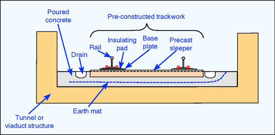
Figure 7: Schematic of slab track showing the principal parts and how they provide the support and protection for the track system. Diagram: Author.
An
earth mat is a steel mesh screen provided on electrified railways to
try to keep stray return currents from connecting to utilities pipes and
nearby steel structures. Earthing must be strictly controlled
otherwise serious and expensive problems of interference and corrosion
will occur, made more serious and expensive because they involve other
people's property.
Some
slab track systems have the sleepers resting on rubber or similar pads
so that they become "floating slab track” (Figure 8). Floating track is
used as a way of reducing vibration. Hong Kong Mass Transit Railway is
fond of it, since its lines run through very densely populated areas.

Figure
8: Floating slab track being installed on the Hong Kong airport railway
of the Mass Transit Railway Corporation. The track is to be lowered
onto rubber pads so that vibration from passing trains is mitigated.
Photo: MTRC.
Ballasted vs Non-Ballasted Track
The basic argument for different track designs will be based on the bottom line - cost; cost of installation and cost of maintenance. There are however, other issues such as environment - noise, dust and vibration - or engineering issues such as space, location, climate and the type of service intended for the track.
There are a wide variety of track forms and systems incorporating some form of concrete base or support which doesn't need ballast. Almost all of these require less depth of construction than ballasted track. However, the accuracy of installation must be higher than that needed for ballasted track. Slab track will not be adjusted after installation but ballast can be packed to align track as required.
The ability of ballast to allow track realignment is one of its most serious weaknesses. The lateral movement caused by passing trains on curved track is one of the major causes of maintenance costs added to which is the crushing caused by axle weight and damage due to weather and water. Ballast damage leads to tracks "pumping" as a train passes and, eventually, rail or sleeper damage will occur, to say nothing of the reduced comfort inside the train and the additional wear on rolling stock. Apart from regular repacking or "tamping", ballast will have to be cleaned or replaced every few years.
Another aspect to the ballasted track design, is the dust which is caused during installation and as it wears or gets crushed. It does however, offer a useful sound deadening quality.
Fixed track formations using slab track or a concrete base of some sort do not suffer from such problems. However, the installation of slab track is reported to cost about 20% more than ballasted track. To balance this cost, the maintenance costs have been quoted as reduced by 3 to 5 times that of ballasted track on a high speed line in Japan.
If low levels of use are foreseen, or if low capital cost is a more important requirement, ballasted track would be the choice. For a heavily used railway, particularly one in a structurally restricted area like a tunnel or viaduct, non-ballasted track must be the best option on grounds of low maintenance cost and reduced space requirements. However, care must be taken during design and installation to ensure the best out of the system. Here is a comparison table for ballasted and slab track and a list of reference railways.
Structures
To ensure that the path required for the passage of trains is kept clear along the route of a railway, a "structure gauge" is imposed (Figure 9). This has the effect of forming a limit of building inside which no structures may intrude. The limit includes not only things like walls, bridges and columns but also pipes, cables, brackets and signal posts. The "structure gauge" will vary with the curvature of the line and the maximum speeds allowed along the section in question.

Figure 9: Diagram of different loading gauges as recorded by the International Union of Railways (UIC). Gauges GA & GB have different shapes up to a height of 4.35 m (14 ft 3 in). GB+ creates a freight network for trailers with ISO containers. Gauge GC is up to 4.70 m (15 ft 5 in) and a width of 3.08 m (10 ft 1 in). All vehicles must stay within a width of 3.15 m (10 ft 4 in) on a 250 m (12 ch) curve. Diagram: UIC.
Although the civil engineer is prevented from allowing his structure to intrude into the train path, the rolling stock engineer also has limits imposed on the space his train may occupy. This space is referred to as the "kinematic envelope". This area designates the limits the train can move laterally and vertically along the route. As for the structure gauge, the kinematic envelope will be affected by speed and features of train design such as the bogie suspension and special systems it may have like tilting car bodies.
Gauging
The line of route has to be checked from time to time to ensure that the structures are not interfering with the gauge. A line is always gauged when a new type of rolling stock is to be introduced. It is important to see that the small variations in track position, platform edge, cable duct location and signal equipment hasn't been allowed to creep inwards during maintenance and renewal programmes.
Gauging used to be done by hand locally (and still is from time to time in special circumstances) but nowadays, it is mostly done with a special train. The train used consist of a special car with a wooden frame built almost to the gauge limits. The edges of the frame were fitted with lead fingers so that, if they hit anything as the train moved along, they would bend to indicate the location and depth of intrusion.
Modern gauging trains are fitted with optical or laser equipment. The optical system uses lights to spread beams of light out from the train as it runs along the line. Suitably mounted cameras record the breaks in the light beams to provide the gauging information. The train can run at up to 50 mi/h (80 km/h) but, of course, the runs have to be done at night. Laser beams are also used but, as they rotate round the train and form a "spiral" of light, the method suffers from gaps which can allow intrusions to be missed.
Monuments and Datum Plates
Along the line of route various locations are marked by a fixed post in the track or a plate on a nearby structure to indicate the correct level or position of the track. These are called monuments or datum plates. Measurements are taken from these to confirm the correct position of the track.
Curves
Curves in the track are almost a science on their own. Careful calculations are required to ensure that curves are designed and maintained properly and that train speeds are allowed to reach a reasonable level without causing too much lateral stress on the track or inducing a derailment. There are both vertical curves and horizontal curves. There is also a section of track on either side of a curve known as the transition, where the track is changing from straight to a curve or from a curve of one radius to one of another radius.
Cant
Cant is the name used to describe the cross level angle of track on a curve, which is used to compensate for lateral forces generated by the train as it passes through the curve. In effect, the sleepers are laid at an angle so that the outer rail on the curve is at a higher level than the inner rail. In the US, it is known as superelevation. A simple description presentation can be seen in the video in Figure 10 below.
Figure 10: An excellent PWay Engineer video demonstrating the details of track cant and cant deficiency. The video is 12:46 minutes long. It is worth the time.
Of course, there will usually be trains of different types, permitted speeds at different levels, which travel the same curve. Also, there will be occasions when trains stop on the curve. This means that the degree of cant has to be fixed at a compromise figure to allow the safety of stopped trains and the best speeds for all the trains using the curve.
In practice, faster trains are allowed to travel round the curve at a speed greater than the equilibrium level offered by the cant setting. Passengers will therefore feel a lateral acceleration similar to what they would feel if there was no cant and the train was travelling at a lower speed round the curve. The difference between the equilibrium cant required by the higher speed and the actual cant is known as the cant deficiency.
Cant is measured either in degrees or in linear dimensions. On standard gauge track (1435 mm or 4ft. 8½ins.) 150 mm or 6 ins. of cant is equal to 6 degrees. This is the normal maximum in the UK. The maximum amount of cant deficiency allowed is 110 mm (4½ ins.).
Turnouts
I
have used the word "turnout" to describe the junctions in trackwork
where lines diverge or converge so as to avoid "points" (UK) or
"switches" (US), both of which terms can be confusing. In the railway
"trade", turnouts are referred to as "switch and crossing work". A
turnout consists of a number of parts as shown in Figure 11.

Figure 11: A diagram showing the parts of a standard turnout or set of points. In the US it is known as a “switch”. The moving parts (shown in red) are moved from one position to another to change the route. Diagram: Author.
The moving part of the turnout is the switch "blade" or "point", one for each route. The two blades are fixed to each other by a tie bar to ensure that when one is against its stock rail, the other is fully clear and will provide room for the wheel flange to pass through cleanly. Either side of the crossing area, wing and check rails are provided to assist the guidance of the wheelsets through the crossing.
Figure 12: Video about how trains change tracks, showing the relationship between wheel and rail through a turnout. The video is 7 minutes long. It was made by Network Rail in Britain.
Crossings
The crossing can be cast or fabricated. Rails are usually made of steel with a large iron content but a little manganese is added to crossings and some heavily used rails to increase resistance to wear. Below is a photo of an example of a cast manganese crossing. A crossing is also sometimes referred to as a "frog".
Examples of Turnouts
The uses of turnouts are wide ranging and cover many variations. A few examples are mentioned below to show the diversity available.

Figure 13: Trap Points are provided at the end of a siding or loop line to protect the main line from a train or vehicles which accidentally pass beyond the limits of the siding. They are normally unpowered trailing points, i.e., they allow a train to pass safely through one direction but will cause the train to be derailed if it passes in the wrong direction. This example shows powered points used to protect a converging junction. Similar points called Catch Points were often provided at the lower end of a gradient to derail runaway vehicles. Photo: Andy F.

Figure 14: High Speed trains require high speed turnouts. Turnouts are designed for 160 km/h (100 mi/h) operation. In the example shown here (on an ICE route in Germany) there are eight point motors to operate the very long and heavy switch blade. Similar turnouts are provided for the TGV high speed lines in France. Photo: Georg Trüb, Railpictures.net.
Point (Switch) Machine
The blades of a turnout are normally moved remotely using an electrically operated point machine. The machine contains the contacts which confirm the points are moved and locked in the correct position for the route set. Point machines are normally located to one side of the track but a new generation of machines is now appearing where the mechanism is contained in a sleeper fitting between the rails.
In some parts of the US, electro-pneumatic point machines are used. They are referred to as switch motors. The London Underground also used e.p. motors. They require an air main to be laid alongside the track and compressors to supply the air. They can also cause problems with condensation due to climatic changes. Often a heater is used to keep the turnout blades free of ice and snow during bad weather.

Figure 15: Points machine next to a turnout. The machine is electric. Photo: Chris McKenna.
Switched Crossing
A switched crossing (sometimes referred to as a swing nose crossing or moveable frog) will normally be provided for turnouts with a very acute angle. The crossing will have a powered element which will be set for the required route at the same time as the switch blade is set.

Figure 16: A switched crossing at Karo Wyo. USA. Photo: M. Decker.
Sources:
Railway Age; Modern Railways; International Railway Journal; Railway Gazette International; Mass Transit; Trains Magazine. Some information was contributed by Dan McNaughton, Simon Lowe and Mike Brotzman.