Introduction
More Information
Train Brakes page on this site.
Vacuum Brake description from the Railcar website.
North American Freight Train Brakes
The Westinghouse Air Brake a 19th century description from the Catskill Archive
The electro-pneumatic (EP) brake was introduced in the early years of the 20th century in an attempt over come the lag in the operation of the pure air brake. Originally designed for subways or metros, electro-pneumatic brake systems are now common on main line passenger railways and on some specialised freight operations. Its main advantage over the air brake is its speed of control and quick on-vehicle reaction times, giving instantaneous control of the whole train to the driver. Its speed of operation makes it ideal for automatic train operation (ATO). EP braking is not the same as ECP braking. ECP brakes have been introduced recently in an attempt to overcome the drawbacks of the air brake system on long freight trains. We discuss ECP brakes later in this article.
Background
Even the most modern, purely air brake systems rely on the transmission of an air signal along the brake pipe. This is initiated from the front of the train and has to be sent to all vehicles along the train. There will always be a time lapse (called the propagation rate) between the reaction of the leading vehicle and the reaction of one at the rear. This time lapse is a considerable restraint on operation. It causes the braking of vehicles to happen at different times along the train so that while some cars are slowing down, others are still trying to push, unbraked, from the rear. When releasing, the front of the train is pulling the rear, which is still braking, and causes stress to the couplers. Another drawback is the lack of a graduated release on older systems, an elusive goal for many years.
The introduction of electric traction and multiple unit control was the spur which eventually produced electrically controlled air brakes. The rise of rapid transit operations in cities, with their high volume and frequent stops and starts, meant that quick responses to brake commands and accurate stopping at stations was an essential ingredient in getting more efficiency. EP brakes first appeared in the US. They were tried on the New York Subway in 1909 and then on London Underground in 1916.
Principles of the E-P Brake
There are many types of e-p brake systems is use today and most of them were developed as an "add-on" to the original air brake system and, as a result, incorporated some common principles in their design as follows:
- The e-p brake operates as the service brake while the air brake is retained for emergency use
- The e-p brake does not compromise the fail-safe or "vital" features of the air brake
- The air brake normally remains in the "Release" position, even while the e-p brake is in "Application" and the same brake cylinders are used.
- E-P brakes are invariably used on multiple unit passenger trains.
- E-P brakes use a number of train wires to control the electrically operated brake valves on each car.
- The train wires are connected to a brake "valve" or controller in the driver's cab.
A Simple E-P Brake System

Figure 1: A schematic of the pneumatic layout of a simple e-p brake system. The standard air brake equipment is retained as the safety system for back-up purposes. A main reservoir pipe is provided along the length of the train so that a constant supply of air is available on all cars. A connection pipe is provided between the main reservoir and the brake cylinders on each car. An "application valve" in this connection pipe will open when required to allow main reservoir air into the brake cylinders. Because the brake pipe is fully charged during an e-p application, the triple valve is in the release position so the brake cylinder is connected to the exhaust. For e-p operation, a "holding valve" is added to the triple valve exhaust. When an e-p application is called for, the holding valve closes and prevents brake cylinder air escaping through the exhaust. Diagram: Author.
EP Control
Electro-Pneumatic brakes are controlled by the driver's brake valve handle. It is usually the same handle used to control the air brake. Electrical contacts are provided so that selection of a position will energise the train wires required to operate the e-p valves on each car (Figure 2). Current to operate the brake control is supplied from a battery through a control switch, which is closed in the operative cab.

Figure 2: Schematic for EP brake control. In the release position, all contacts are open and the e-p valves on each car are de-energised. In the "Application" position, the holding and application wires are energised and both valves will be energised on each car to cause the brakes to apply. Note that the contact for the holding wire is arranged to close first so that no air will escape when the application valve is opened. In the "Holding" position, only the holding wire is energised. In effect, the driver can add or subtract air at will and can obtain an infinite variety of braking rates according to the requirements of each stop. Diagram: Author.
Brake Cylinder Pressure
It is essential to ensure that, during braking, the train wheels do not skid. Skidding reduces the braking capability and it damages wheels and rails. Wheels involved in a skid will often develop "flats", a small flat patch on the tyre which can normally only be removed by reprofiling the wheel in a workshop. To reduce the risk of skidding, brake cylinder pressure must be restricted. In a pure air brake system, a natural restriction is imposed by the maximum allowed brake pipe pressure and in the proportion of volume between the auxiliary reservoir and the brake cylinder. In an EP equipped train, the main reservoir supply may not restricted, so it would be possible to go on pumping air into the brake cylinder until it burst. Of course, this will not happen because the brake cylinder is fitted with a safety valve (not shown in the diagram) set at the maximum pressure normally obtained in full braking.
E-P Variations
There have been a number of developments of the e-p braking system over the years, including a common addition - the "Self Lapping" brake. There have also been "retardation controllers" and, more recently, variable load control and single wire or P-wire control.
Self Lapping Brakes
A "self lapping" brake is really a brake controller (brake stand or brake valve, call it what you will) in the driver's cab, where the position of the brake handle between "Release" and Application" corresponds to the brake rate achieved by the equipment - in theory at least. This is similar in principle to the self lapping control valves fitted to some air braked locomotives. A number of different systems have been adopted, including one which uses a pressure sensitive valve detecting brake cylinder pressure and comparing it with the position of the brake handle. When the pressure corresponds to the position of the brake handle, the application electrical connection is opened to keep the brake cylinder pressure at that level.
Another version was developed, using a mercury filled tube inside the brake controller. The mercury was used to conduct the control current to the application and holding wires. The shape of the tube was oval and it was aligned "forward and aft" so it allowed the mercury to flow forward if the train started braking. When "Application" was called for, the movement of the brake handle towards full application tilted the mercury tube backwards and caused the holding and application valves to be energised. As the train brakes applied, the mercury detected the slowing of the train and it ran forward in the tube. This had the effect of cutting off the application so that the rate of braking conformed to the angle of the tube set by the driver's movement of his brake handle.
Retardation Controller
The mercury brake controller was an adaption of a device introduced to London Underground in the mid-1930s called the "mercury retarder" or "retardation controller".
The mercury retarder is a dynamic switch set into the e.p. brake application circuit, comprising a glass tube filled with mercury. It is mounted parallel to the motion of the train so that the mercury fluid reacts to the train's braking. The tube is curved so that the electrical contact at the base is always covered with mercury but a second contact, set higher up the rear of the tube, becomes exposed when the mercury runs forward during braking. It has the effect of measuring the deceleration rate. It cuts off application at a pre set level, no matter how much more the driver tries to put into the brake cylinders. Its main purpose was to reduce flatted wheels. It also acted as a crude form of load compensation.
In the London Underground version, two retarders were provided and they were stationary, being fixed in the driving car. They were used to regulate the rate of braking at the full application end of the range, primarily to reduce skidding and the dreaded "flats" on wheels. One retarder limited the application while the second was used to reduce the brake cylinder pressure by releasing some air through a special "blow down" valve.
Retardation controllers were later used to control braking rates on the world's first ATO railway, the Victoria Line. Four were used in all, each being set at a different angle and selected as necessary to give the required braking rate. They were also used by British Rail as self-lapping brake controllers provided on the EMU stocks built in the 1960s and 70s.
Variable Load Control
Although the retardation controller is a form of load control - because the braking rate is monitored, a heavier train will require more brake cylinder pressure, so the retarder will not reach its setting until the right rate is reached - it is rather crude. It only monitors the whole train, not individual cars. This means that lightly loaded cars in a generally heavy train are still at risk from a skid or wheelslide, as it is called. The solution is in variable load control. The car weight is monitored, usually by a lever fitted between the car and the bogie, which detects the bogie spring depression as weight increases. The lever is connected to a regulating valve in the brake cylinder feed pipe, so that the brake cylinder pressure is varied in relation to the weight of the car. With the introduction of air suspension, load control is achieved by monitoring the level of air in the suspension system and regulating brake cylinder pressure accordingly. Nowadays, the same load signals are used to vary acceleration and dynamic braking according to car weight.
P-Wire Control
As train control systems grew more complicated, more train wires were required and the traditional 10-wire jumper used by so many railways grew to the 27-wire or 40-wire jumper often seen today. In an attempt to reduce wiring, a novel form of e-p brake control appeared in the 1970s called the P-wire system. The brake rate was controlled by a single wire carrying pulses of different lengths to correspond to different brake rates. The pulse width was modulated to correspond to the brake demand required and it became know as the PWM (Pulse Width Modulation) system or P-wire, for short. The system was "fail-safe" in that no pulse activated the full brake while a continuous pulse kept the brake released.
Three-Step Brake
Another development for electrical brake control was the 3-step system adopted on British railway EMU trains in the 1970s. It was based on the Westcode 7-step brake system where three steps were taken for service braking use. These were broadly described as minimum, normal and full service braking. With the addition of “Release” and “Emergency” the full range of braking controls were provided. It also eliminated the need for a brake pipe.

Figure 3: Schematic of electro-pneumatic brake system without a brake pipe or triple valve. The braking continuity of the train is based on the provision of a “round the train” wire that is connected to the brake controls to ensure that if the train becomes uncoupled or any brake control defects occur, the train brakes will automatically apply. Diagram: Author.
Brake Blending
Most trains are now provided with a combination of friction braking and dynamic braking. The dynamic braking system uses the electric traction motors of the locomotive or train to provide a braking effort by reversing the electrical connections so that the motors become generators. The energy generated by the motors is fed into on-board resistors (rheostatic braking) or back into the electric traction supply system (regenerative braking).
Dynamic braking only operates on wheelsets that have electric motors. Other wheelsets need to be provided with friction braking and, in case the dynamic braking ins’t available, the friction brake is provided on motored axles too. The control of the two brake systems is managed automatically by a brake blending system.
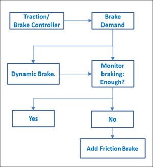
Figure 4: Schematic of basic brake control blending system. The control on each vehicle will include an additional load monitor to adjust the brake according to the vehicle load. Diagram: Author.
The brake blending system is set up so that, when the driver (or the ATO system, if the train is automatically controlled) calls for brake, the dynamic brake is the preferred option. This is because it can save energy through regeneration and it reduces wear on brake pads or brake shoes and on discs and wheels. If the dynamic brake meets the brake demand, the friction brake is held off. If the dynamic brake effort is unable to meet the demand called for, the friction brake is added as necessary. The feedback loop that this arrangement incorporates provides a blended brake application that will always meet the demand.
PBL90 System
No survey of the electro-pneumatic brake would be complete without a reference to the European system known as PBL90. This is not a pure e-p brake system as used on metros and suburban systems but more of an electrically assisted air brake control system. It is designed to allow vehicles with no electro-pneumatic brake controls to operate in a train with e-p control available on the locomotive or power car. For a description of the control system including diagrams, go to the PBL90 EP Brake Control Page.
Electronically Controlled Pneumatic (ECP) brakes
A new form of electrical control of air braking is currently being tested by a number of railroads in the US. It is known as ECP and uses modern electronic techniques to overcome the problems of air braking on long freight trains.
The pure air control brake system invented by George Westinghouse in the 1860s and still used by almost all freight trains in the US and in many other parts of the world suffers from two main problems. It takes a long time for the air messages to travel along the train and there is no graduated release. For example, the delay for a reduction in train line pressure to travel from the leading locomotive to the rear of a 150 car consist can be 60 seconds. Also, you have to fully release the brake and wait for the supply reservoirs to recharge before you can reapply. Electrical control can overcome these difficulties.
ECP refers to Electronically Controlled Pneumatic brakes, key word being "Electronically" as opposed to "electrically". Older systems fitted to passenger trains (see above), use several train wires to operate individual valves or variations in switching of the wires to control brakes. Most of these systems use a second train line for main reservoir air supplies and they do not have the built-in two-way communications that ECP systems have. A car in an ECP brake train can do a self-diagnosis and report the information to the engineer and it only requires the standard train line pipe.
Operation of ECP
There is a control box on top of the engineer's console. When he wants to apply brakes the engineer pushes the button until the readout shows the amount of brake cylinder pressure (or percentage of braking effort) he wants. He releases the button; the control unit then codes and sends the signal to all cars. They in turn receive and interpret the message. They then begin allowing compressed air from their reservoirs to go to the brake cylinder until the desired cylinder pressure is achieved. The microprocessors on the cars will continuously monitor brake cylinder pressure against leakage and maintain the desired pressure.
If the engineer wants to reduce brake cylinder pressure he simply pushes the release button until the desired level is indicated, either partial or full release. Again a signal is coded and transmitted to the cars. The cars in turn do as commanded. If the engineer asks for only a partial reduction of braking effort, he can increase the effort again as needed without doing a full release first. The processor on the car is constantly monitoring brake pipe, reservoir tank and brake cylinder pressures.
When braking commands are not being transmitted, the head end (control) unit is sending out status messages. The last car in the train (which knows it is last due to the head end doing a train query and initialisation at start-up) will respond to each status message from the head end. All cars in the consist will monitor these messages, and if a car fails to receive three status messages in a row from either the head end or the rear end, it will assume that the train is broken in two or that the electrical line is broken. It will then initiate an emergency stop, while trying to tell the other cars and loco that it is doing so.
Power Sources for ECP
Each car has a rechargeable battery to provide the high power requirements when solenoids need to be activated. When the high power is not being used, the batteries will trickle recharge from the communications/power cable. (If the train uses radio communication the batteries will recharge while the car is in motion via an onboard generator creating power from the motion of the car, either an axle generator, or natural frequency vibration generator or some other type of device.)
The hardwired system uses roughly 25% of its signal capacity for brake commands and status messages. Distributed power, controlled via the same cable uses another 10-15%, leaving 60-65% of the signal capacity for special monitors on the car, such as bearing sensors, temperature sensors for reefers on tankers, pressure sensors for tankers, etc.
Manufacturers Systems
TSM, which was a subsidiary of Rockwell International, developed the first working ECP brake units. They are now owned by WABCO. In addition, Westinghouse Air Brake, New York Air Brake (a subsidiary of Knorr Corp.), GE/Harris and a small company called Zeftron, are developing ECP units.
TSM's first units worked in an "overlay" mode, where a module was placed between the air pilots and the actual valves, so that the system could work both ways. Zeftron started out working on an "emulator" brake valve, which totally eliminates the air pilots. The system, which must always be powered, looks for ECP commands. If it finds none, it monitors brake pipe pressure and behaves just like a standard air brake. If ECP command signals are present, the units behave like an ECP brake.
Because of the sequential operations of standard brakes, there is a flow control which limits how fast the air can flow into the brake cylinder. On ECP systems, because there is instantaneous reaction from all cars at once, these flow controls are not used. The lack of sequential activation and flow controls combined is what makes ECP brakes so responsive.
TSM is now introducing an emulator system. This enables cars fitted with it to work in ECP trains and non-ECP trains. New York Air Brake has a system available for sale in the very near future. Westinghouse Air Brake is playing it cool, waiting for all of the specs to be written and all of the bugs worked out before they commit to anything.
Benefits
Some of the benefits of ECP braking have already been mentioned; instantaneous response to the engineer's commands on all vehicles, graduated release of brakes and continuous replenishment of reservoirs. But there are other and more significant benefits for the industry as a whole.
With the new responsiveness of ECP braking, braking distances will be reduced. A range of 30 - 70% reduction has been quoted. This will allow shorter stopping distances and will, in turn, allow higher speeds. The improved train handling will reduce slack action, breakaways and derailments and will lead to a reduction in draft gear maintenance.
There may be a price to pay. Although the current view is that brake shoe and wheel wear will be reduced, it is easy to see that engineers will develop their handling skills with the new system and this will lead to higher speeds needing more and heavier brake applications. A wise railway management will recognise this and will review its speed limit zones to ensure the maximum benefits are obtained without excessive brake usage.
Developments
There was much discussion amongst experts regarding the need for an end-of-train (EOT) device or letting the last car act as the end-of-train beacon. It seems that the last word on EOT beacons was that there will be one!
There are committees that are developing specs right now to permit the addition of monitors onto cars. The monitors will have their own microprocessors and will only send a signal to the head end when something on the car is going out of specified limits. This keeps the communications line open for brake commands, loco commands, and emergency messages.
A further development will be the use of the electronic train line for diagnostics, where the head end position can be informed of hot boxes, car load temperatures, tanker pressures, wagon doors not closed, parking brake off/on and the like.
ECP Record
There was a record-breaking, 600 km round trip by a train fitted with ECP braking in Australia. On 28 June 1999, a train comprising 240 wagons, five GE Dash 8 diesel-electric locomotives and weighing 37,500 tonnes was equipped with the GE Harris EPx radio-based, electronic brake control system. It was the longest and heaviest train ever to be fitted with an ECP brake system. The locomotives were fitted with the same company's Locotrol remote locomotive control system. The train operated over the BHP Iron Ore line between Port Headland and Yandi Mine. Source IRJ.