Railway signalling is a complex and fascinating subject. This site has a number of pages explaining the signalling and train control systems in use around the world ranging from old semaphore signals still used in the UK and elsewhere to modern electronic high capacity systems used by metros. We also provide links to other railway signalling sites around the world that describe local systems.
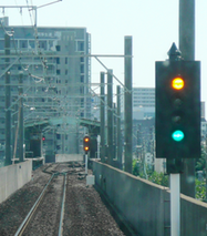
Figure 1: Colour light signals on a local railway in Japan. Photo: PekePON.
Background
Signalling is one of the most important components of the many which make up a railway system. Train movement safety depends on it and the control and management of trains depends on them. Over the years many signalling and train control systems have been evolved so that today a highly technical and complex industry has developed. Here is an attempt to explain, in simple terms, how railway signalling developed and how it really works, based on the UK standards.
Pioneer Signalling
Back in the 1830s and 40s (in the very early days of railways) there was no fixed signalling - no system for informing the driver of the state of the line ahead. Trains were driven "on sight". Drivers had to keep their eyes open for any sign of a train in front so they could stop before hitting it. Very soon though, practical experience proved that this didn’t work and there needed to be a way of preventing trains running into each other. Several unpleasant accidents had shown that there was much difficulty in stopping a train within the driver's sighting distance. The problems were, partly, inexperience and poor brakes but the real problem was (and still is) the rather tenuous contact which exists on the railway between steel wheel and steel rail for traction and braking. The adhesion levels are much lower and vehicle weights much higher on railways than on roads and therefore trains need a much greater distance in which to stop than, say, an automobile travelling at the same speed. Even under the best conditions, it was (and is even more so nowadays with high speeds) often impossible to stop a train within the sighting distance of its driver.
The Time Interval System
In the early days of railways, it was thought that the easiest way to increase the train driver's stopping distance was to impose time intervals between trains. Most railways chose something like 10 minutes as a time interval. They only allowed a train to run at full speed 10 minutes after the previous one had left. They ran their trains at a 10 minute "headway" as it is called.
Red, yellow and green flags were used by "policemen" to show drivers how to proceed. A red flag was shown for the first five minutes after a train had departed. If a train arrived after 5 minutes, a yellow caution signal was shown to the driver. The full-speed green signal was only shown after the full 10 minutes had elapsed.
The "time interval system", in trying to use a headway to protect trains, actually created some serious problems of its own. The most serious was that it was still inherently dangerous. Trains in those days were considerably less reliable than they are today and often broke down between stations. It also could not be guaranteed that the speed of the first train would be sufficient to prevent the second catching it up. The result was a series of nasty rear-end collisions caused, in each case, because the driver believed he had a 10 minute gap ahead of him and had little or no warning if there was an erosion of that 10 minutes. Even if the time was reduced so much that he could see the train in front, he often did not have enough braking capacity to avoid a collision.
Line Capacity
Another serious problem, from the railways' point of view, was line capacity. Even if they could rely on their trains not to make unscheduled stops and all to travel at the same speed, the 10 minute time interval restricted the number of trains which could run per hour (in this case 6) over a given line. As they found they needed to run more trains, they gradually began to reduce the time between trains. As they reduced the time, or "headway", the number of trains per hour increased. At the same time too, the number of accidents increased. Eventually, they realised they had to do something. The answer was fixed signalling.
Fixed Signalling
Even with the old time interval system, the basic rule was to divide the track into sections and ensure that only one train was allowed in one section at one time. This rule is still good today. Each section (or block as it is often called) is protected by a fixed signal placed at its entrance for display to the driver of an approaching train. If the section is clear, e.g. there is no train in it, the signal will show a "Proceed" indication. For many years in Britain it was usually a raised or lowered semaphore arm (Figure 2). There are a few of these left around the country but nowadays it is usually a green light or "aspect", as the railways call it. If, however, the section is occupied by a train, the signal will show a "Stop" indication, usually a red aspect. The next train will be made to wait until the train in front has cleared the section. This is the basis upon which all signalling systems are designed and operated.
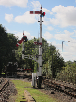
Figure 2: Photo of typical railway semaphore signals at the Great Western Society site at Didcot, Oxfordshire, UK. The signal on the right displays a stop command, while the one on the left displays 'proceed’ for the diverging route on the left. Photo: Author.
Mechanical signals first appeared in the UK in 1841 and a signal box with levers controlling remote signals and points in 1860. Originally, the passage of each train through a section was tracked visually by the signalman. When the train had cleared his section, the signalman told the signal box on the approach side that his section was now clear and that he could, if required, "accept" another train. The messages between signal boxes were transmitted by a system of bell codes using the electric telegraph.
Compulsory use of the electric "block telegraph" to pass messages, and signal interlocking, where points and signals were mechanically prevented from allowing conflicting movements to be set up, were introduced in the UK following the Regulation of Railways Act of 1889.
Distant Signals
The basic stop/go signal used to protect each section of the line was OK as long as the driver of an approaching train was able to see the signal in time to stop. This was rarely the case, so a system of "distant" signals was provided in many locations.
Distant signals were placed in such a position that the driver could stop in time if the next stop signal was at danger. Positioning depended on the visibility, curvature, maximum permitted line speed and a calculation of the train's ability to stop. In the UK, freight trains with reduced braking capacity (unfitted or partially fitted freights) were only allowed to run at restricted top speeds to allow for signal braking distances.
Originally, distant signals were semaphores, like the stop signals mentioned above. They showed a green light at night if their related stop signal was also green (or clear) and yellow if the stop signal was at red. The red-yellow-green pattern was adopted for colour light signals and eventually used to provide a more spohisticated form of train control.
Interlocking
Another safety feature introduced in the mid-19th Century was mechanical interlocking of points and signals. The purpose was to prevent the route for a train being set up and its protecting signal cleared if there was already another, conflicting route set up and the protecting signal for that route cleared. The interlocking was performed by a series of mechanically interacting rods connected to the signal operating levers in the signal box. The arrangement of the rods physically prevented conflicting moves being set up. As the systems developed, some larger signal cabins at complex junctions had huge frames of interlocking levers, which gave the name "lever frame" to the row of operating levers in a signal box.
Eventually, by the time signal levers were being replaced by small (miniature) levers or push buttons, mechanical interlocking frames were superseded by relay interlockings. Electro-magnetic relays were used in series to ensure the safety of route setting at junctions. Complex "control tables" were drawn up to design the way in which these relays would interact and to ensure safety and integrity. Now, most of this is computerised.
Blocks

Figure 3: Schematic of signal block section. When a block is unoccupied, the signal protecting it will show green. If a block is occupied, the signal protecting it will show red. Diagram: Author.
Railways are provided with signalling primarily to ensure that there is always enough space between trains to allow a following train to stop before it hits the one in front. This is achieved by dividing each track into sections or "blocks". Each block is protected by a signal placed at its entrance. If the block is occupied by a train, the signal will display a red "aspect" as we call it, to tell the train to stop. If the section is clear, the signal can show a green or "proceed" aspect.
The simplified diagram (Figure 3) shows the basic principle of the block. The block occupied by Train 1 is protected by the red signal behind it at the entrance to the block. The block behind (“in rear”, as it is known) is clear of trains and a green signal will allow Train 2 to enter this block. This enforces the basic rule or railway signalling that says only one train is allowed onto one block at any one time.
The Track Circuit
Nowadays for signalling purposes, trains are monitored automatically by means of "track circuits". Track circuits were first tried in the US in the 1890s and soon afterwards appeared in Britain. London Underground was the first large-scale user of them when they introduced them in 1904-6 as part of their electrification programme.
Low voltage currents applied to the rails cause the signal, via a series of relays (originally) or electronics (more recently) to show a "proceed" aspect. The current flow will be interrupted by the presence of the wheels of a train. Such interruption will cause the signal protecting that section to show a "stop" command. Any other cause of current interruption will also cause a "stop" signal to show. Such a system means that a failure gives a red aspect - a stop signal. The system is sometimes referred to as "fail safe" or "vital". A "proceed" signal will only be displayed if the current does flow. Most European main lines with moderate or heavy traffic flows are equipped with colour light signals operated automatically or semi-automatically using track circuit train detection.
Track Circuit - Block Unoccupied

Figure 4: This diagram (right) shows how the track circuit is applied to a section or block of track. A low voltage from a battery is applied to one of the running rails in the block and returned via the other. A relay at the entrance to the section detects the voltage and energises to connect a separate supply to the green lamp of the signal. Diagram: Author.
Track Circuit - Block Occupied

Figure 5: When a train enters the block (right), the leading wheelset short circuits the current, which causes the relay to de-energise and drop the contact so that the signal lamp supply circuit now activates the red signal lamp. The system is "fail-safe", or "vital" as it is sometimes called, because any break in the circuit will cause a danger signal to be displayed. Diagram: Author.
The above provides a simplified description of the track circuit. The reality is somewhat more complex. A block section is normally separated electrically from its neighbouring sections by insulated joints in the rails. However, more recent installations use electronics to allow jointless track circuits. Also, some areas have additional circuits which allow the signals to be manually held at red from a signal box or control centre, even if the section is clear. These are known as semi-automatic signals. Even more complexity is required at junctions.
Multi-Aspect Signals
The basic, two-aspect, red/green signal is fine for lower speed operation but for anything over about 50 km/h the driver of a train needs a warning of a red signal ahead to give him room to stop. In the UK, this led to the idea of caution signals (originally called "distant" signals when they were mechanically operated semaphore arms) placed far enough back from the signal protecting the entrance to the block to give the driver a warning and a safe braking distance in which to stop. When this was developed for track circuited signalling, the caution signal was provided a block further back from the stop signal. Each signal would now show a red, yellow or green aspect - a multi-aspect signal.

Figure 6: Schematic of 3-aspect signalled route showing the additional yellow aspect provided to allow earlier warnings and thus higher speed operation. Diagram: Author
The diagram (Figure 6) shows a line with 3-aspect signals. The block occupied by Train 1 is protected by the red signal at the entrance to the block. The block behind is clear of trains but a yellow signal provides advanced warning of the red aspect ahead.This block provides the safe braking distance for Train 2. The next block in rear is also clear of trains and shows a green signal. The driver of Train 2 sees the green signal and knows he has at least two clear blocks ahead of him and can maintain the maximum allowed speed over this line until he sees the yellow.
Four-Aspect Signalling
The multi-aspect signalling commonly used in the UK today is a 4-aspect system. It works similarly to the 3-aspect system except that two warnings are provided before a red signal, a double yellow and a single yellow. This has two purposes. First, it provides early warnings of a red signal for higher speed trains or it can allow better track occupancy by shortening the length of the blocks. The high speed trains have advanced warning of red signals while the slower speed trains can run closer together at 50 km/h or so under "double yellows".

Figure 7: Schematic (right) of 4-aspect signalled route showing how the double-yellow aspect works. The upper diagram shows four-aspect signals with a high speed train with three clear blocks ahead of it and then, in the lower diagram, a slower train with two clear blocks ahead of it. The lower speed trains can run closer together so more trains can be operated over a given section of line. Daigram: Author.
A Safe Braking Distance
The foregoing description of signalling has so far only looked at the concept of warning or enforcement of restrictive signal indications. It has not yet taken into account braking distance or headway. First, there is the problem of braking distances. As we have already seen, a train cannot stop dead. An Inter City train travelling at 100 mph (160 km/h) can take more than a mile to stop. Even for a signalling system with enforcement (ATP) like the London Underground, as described so far there is a risk that a train could pass a stop signal, then be stopped by the ATP enforcement system and still hit the train in front. This situation could occur if the train in front was standing just ahead of the signal protecting it. The problem has long been recognised and can be overcome by the provision of a space for the train to stop in, an "overlap".
The Overlap
In its simplest form, the overlap is a distance allowed for the train to stop in should it pass a signal showing a stop aspect. It is provided by positioning the signal some way before the entrance to the section it is protecting.

Figure 8: Photo of typical British railway 4-aspect colour light signal showing a double yellow aspect. The bottom lens is for the red aspect and the one between the two yellows is for the green. Photo: WBSS Co.
On railways in Britain, because it is impossible to calculate all the various braking distances of different types of trains and because it is impossible to predict when a driver might react to a stop signal, a fixed value of 200 yards (185 metres) is normally used where space allows. On metros that use ATP systems, the distance is calculated by a precise formula based on the known braking capacity of the metro train, the gradient at the location concerned, the maximum possible speed of the trains using that section, an allowance for the sighting of the signal by the driver and a small margin. The result of the calculation is called the "safe braking distance". The overlap incorporates this safe braking distance.