Bogies (Trucks)
More Information
Railway bogies are hardly noticed by the average passenger but they are an essential part of the the train, its drive system and its guidance mechanism. A standard railway vehicle will have two bogies, generally located near the vehicles ends. Each bogie is a 4-wheeled or 6-wheeled truck that provides the support for the vehicle body and which is used to provide its traction and braking. Each carriage (called a car in North America and some other English speaking countries and still so called in the electric traction business) has two bogies. The bogies support the mass of the vehicle, use the wheels to guide it along the track and provide some degree of cushioning against the shocks transmitted from the track during motion. See also Vehicle Suspension Systems.
Bogies may be powered, either by electric motors of some type of mechanical drive connected to a motor of diesel engine. They may also just provide the carrying function - so-called trailer bogies. Both motor and trailer bogies are normally braked, under the control of the train braking system.
A pair of train wheels is rigidly fixed to an axle to form a wheelset. The wheels are pressed on to the axle so that they both rotate together. As we’ve seen above, normally two wheelsets are mounted in a bogie, so the bogie is simply a 4-wheeled truck – the Americans call it a truck – mounted under a railway carriage in order to support and guide the carriage along the track.

Figure 1: A standard American 3-piece bogie as used on freight cars around the world. This design is very simple, where the transverse member known as the bolster sits on a pair of twin coil springs to provide some level of damping for the vehicle resting on the two side bearers. The bogie rotates around the centre pin to allow the bogie to negotiate curves. Passenger bogies have additional springs on the axleboxes. Diagram: Amsted, modified by Author.
A standard freight car bogie is shown in Figure 1. It is simple and has only one suspension system. A passenger bogie also has springs mounted on the top of the axleboxes of the wheelsets. These axlebox springs are known as the primary suspension. The bolster springs are known as the secondary suspension. The car body is therefore separated from the track by two sets of springs (Figure 2).

Figure 2: Simple schematic of passenger car suspension system showing the general arrangement and location of the primary suspension springs on the axleboxes and the secondary suspension upon which the car body rests. Diagram: Author.
Traditionally, springs were steel, either coil or flat. Nowadays they are often rubber or compressed air bags or some sort of combination. In passing, we should not forget that railway wheels come in pairs fixed to a common axle the correct distance apart (the gauge) and the whole rigid system is called a wheelset (Figure 3). The traditional bogie frame consists of two side frame pieces and two headstocks forming a box structure. To add strength, a pair of cross members, called transoms, are added.
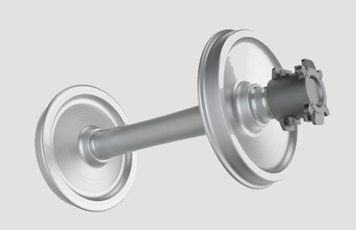
Figure 3: A typical railway wheelset with axleboxes. The wheels are pressed on to the axle and then the axleboxes are pressed on. Photo: Danobat.
Steerable Bogies
A conventional bogie frame is turned into the curve by the leading wheelset as it is guided by the rails. However, there is a degree of slip and a lot of force required to allow the change of direction. The bogie is, after all, carrying about half the weight of the vehicle it supports. It is also guiding the vehicle, sometimes at high speed, into a curve against its natural tendency to travel in a straight line.
To overcome some of the mechanical problems of the rigid wheelset mounted in a rigid bogie frame, some modern designs incorporate a form of radial movement in the wheelset (Figure 4).
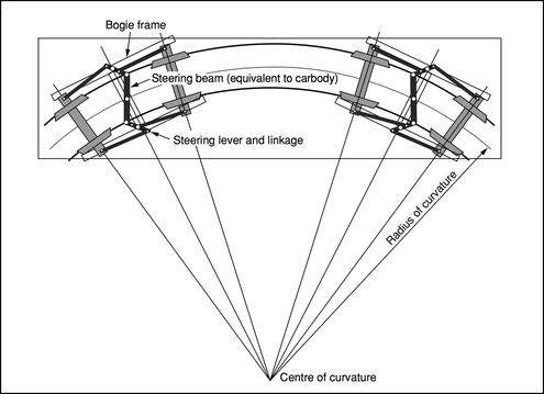
Figure 4: A design for a steerable bogie. In this Japanese design the axles are allowed a degree of movement in the bogie frame and the axleboxes are linked to the car body through a steering beam. There are a number of different systems for reducing wheel wear and bogie frame stress and this is one of the early systems. Diagram: JRTR F52.
A Motor Bogie
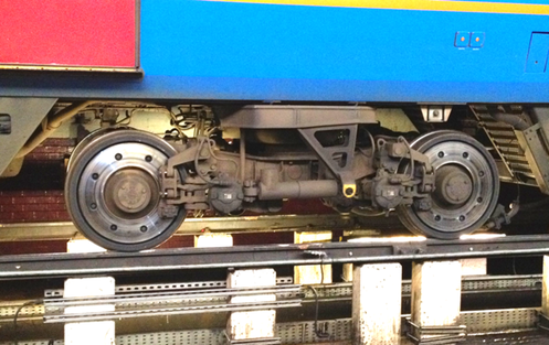
Bogies come in many shapes and sizes but it is in its most developed form as the motor bogie of an electric or diesel locomotive or an EMU. Here it has to carry the motors, brakes and suspension systems all within a tight envelope. It is subjected to severe stresses and shocks and may have to run at over 300 km/h in a high speed application. The following paragraphs describe the parts shown on the photograph below, which is a UK design.

Figure 5: An electric traction motor bogie with a welded steel frame and nose suspended traction motors. The parts named here are described in the following paragraphs.
Bogie Frame
Can be of steel plate or cast steel. In this case, it is a modern design of welded steel box format where the structure is formed into hollow sections of the required shape.
Bogie Transom
Transverse structural member of bogie frame (usually two off) which also supports the carbody guidance parts and the traction motors.
Brake Cylinder
An air brake cylinder is provided for each wheel. A cylinder can operate tread or disc brakes. Some designs incorporate parking brakes as well. Some bogies have two brake cylinders per wheel for heavy duty braking requirements. Each wheel is provided with a brake disc on each side and a brake pad actuated by the brake cylinder. A pair of pads is hung from the bogie frame and activated by links attached to the piston in the brake cylinder. When air is admitted into the brake cylinder, the internal piston moves these links and causes the brake pads to press against the discs. A brake hanger support bracket carries the brake hangers, from which the pads are hung.
Primary Suspension Coil
A steel coil spring, two of which are fitted to each axlebox in this design. They carry the weight of the bogie frame and anything attached to it.
Motor Suspension Tube
Many motors are suspended between the transverse member of the bogie frame called the transom and the axle. This motor is called "nose suspended" because it is hung between the suspension tube and a single mounting on the bogie transom called the nose.

Figure 6: Drawing of a nose suspended traction motor. The motor drives the axle through a pinion/gearwheel set, with the gearwheel pressed onto the axle. The motor weight is distributed between the transom of the bogie and the axle. The axle carries the weight of the motor through a suspension tube. Drawing: Voith.

Figure 7: A more modern design is the frame mounted motor. The weight of the motor is carried entirely by the bogie frame. The axle is driven through a flexible coupling. This arrangement reduces the unsprung weight on the wheels and therefore reduces wear. Drawing: Voith.
Gearbox
This contains the pinion and gearwheel which connects the drive from the armature to the axle.
Lifting Lug
Allows the bogie to be lifted by a crane without the need to tie chains or ropes around the frame.
Motor
Normally, each axle has its own motor. It drives the axle through the gearbox. Some designs, particularly on tramcars, use a motor to drive two axles
Neutral Section Switch Detector
In the UK, the overhead line is divided into sections with short neutral sections separating them. It is necessary to switch off the current on the train while the neutral section is crossed. A magnetic device mounted on the track marks the start and finish of the neutral section. The device is detected by a box mounted on the leading bogie of the train to inform the equipment when to switch off and on.
Secondary Suspension Air Bag
Rubber air suspension bags are provided as the secondary suspension system for most modern trains. The air is supplied from the train's compressed air system.
Wheel Slide Protection System Lead to Axlebox
Where a Wheel Slide Protection (WSP) system is fitted, axleboxes are fitted with speed sensors. These are connected by means of a cable attached to the WSP box cover on the axle end.
Loose Leads for Connection to Carbody
The motor circuits are connected to the traction equipment in the car or locomotive by flexible leads shown here.
Shock Absorber
To reduce the effects of vibration occurring as a result of the wheel/rail interface.
Axlebox Cover
Simple protection for the return current brush, if fitted, and the axle bearing lubrication.
Bogie Designs
There are a number of different designs for bogies as shown in the following illustrations.
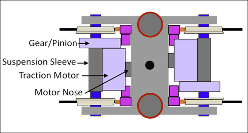
Figure 8: A bogie with a welded H-form frame equipped with two electric motors mounted in the "nose suspended” configuration where the motor mass is shared between the bogie transom and the axle it is driving. In this design the secondary suspension uses air bags. The air bags are filled with compressed air supplied from the on-board air compressor. Drawing: Author.
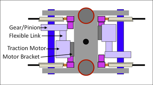
Figure 9: A bogie with a welded H-form frame equipped with two electric motors mounted in the “frame mounted” configuration where the motor mass is largely carried by the bogie frame. Drawing: Author.
Figure
10: A bogie under a British Class 222 diesel electric multiple unit.
This has an inside frame design so that the wheels are almost totally
exposed from the outside. The brake discs are obvious with the brake
actuators mounted around the inside of each wheel. There is a large horizontal torsion bar connecting the car body to the bogie frame in
order to reduce sideways motion or “hunting”. Photo: Author.

Figure 11: A tramcar bogie of the Bombardier Flexx 3000 type. The need for low floors on modern tramcars and light rail vehicles forces a very compact design. Here the traction motors are small and are mounted outside the bogie, driving the axle end through a 90 degree gearbox. Brake discs and actuators are also mounted outside the wheels. This bogie was designed for the Blackpool tram. Photo: Author.
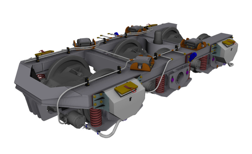
Figure 12: A 3-axle bogie drawn using CAD. The function of a 3-axle bogie is the same as a 2-axle bogie but the additional axle is needed to distribute a larger mass over the track. The weight limits for track are defined as axle weight, i.e. the weight allowed to be carried on each axle. The maximum axle weight for main lines in the UK is 25 tonnes, in Europe 22.5 tonnes. On heavy haul freight routes it can be up to 36 tons. The disadvantage of the 3-axle bogie is the long rigid wheelbase, which limits the curve radius that can be used. Drawing: 3dcadbrowser.com.
Jacobs Bogie
The Jacobs bogie is an arrangement where one bogie supports the ends of two adjacent vehicles. The name is derived from the German railway engineer Wilhelm Jakobs (1858–1942). Versions of it are used on both freight and passenger vehicles.
The general arrangement appears as shown in Figure 13.
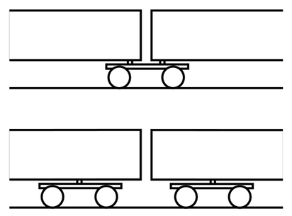
Figure 13: A schematic showing the difference between a Jacobs bogie supporting the ends of two adjacent cars (upper drawing) and a conventional design where each car end is supported by its own bogie (lower drawing). The Jacobs idea provides for a reduced number of bogies for a set of vehicles but has the disadvantages of higher axle weight and a more complex design. It also requires special measures for lifting vehicles. Drawing: Wikipedia Fr 2008.