Introduction
Useful Links
There is a wide variety of electric traction systems around the world and these have been built according to the type of railway, its location and the technology available at the time of the installation. Many installations seen today were first built more than 100 years ago, some when electric traction was barely out of its diapers, so to speak, and this has had a great influence on what is seen today.
In the last 20 years there has been a rapid acceleration in railway traction development. This has run in parallel with the development of power electronics and microprocessors. What had been the accepted norms for the industry for sometimes, 80 years, have suddenly been thrown out and replaced by fundamental changes in design, manufacture and operation. Many of these developments are highly technical and complex, the details of which are therefore beyond the scope of these texts.
Because the changes have been so rapid, there are still plenty of examples of the original technology around and in regular use, so I have covered these in my articles. This is useful, since it helps the reader to get to grips with the modern stuff.
Power Supply
To begin with, the electric railway needs a power supply that the trains can access at all times. It must be safe, economical and user friendly. It can use either DC (direct current) or AC (alternating current), the former being, for many years, simpler for railway traction purposes, the latter being better over long distances and cheaper to install but, until recently, more complicated to control at train level.
Transmission of power is always along the track by means of an overhead wire or at ground level, using an extra, third rail laid close to the running rails. AC systems always use overhead wires, DC can use either an overhead wire or a third rail; both are common. Both overhead systems require at least one collector attached to the train so it can always be in contact with the power. Overhead current collectors use a "pantograph", so called because that was the shape of most of them until about 30 years ago. The return circuit is via the running rails back to the substation. The running rails are at earth potential and are connected to the substation.

Figure 1: A section of the Old Dalby test track in England showing both third rail and overhead electrification. Both systems are provided to allow train testing from the main line or London Underground. The 3rd rail system is common around the world but the 4th rail is rare. London Underground is the largest user of the 4-rail system in the world. Photo: Author.
Shoes and Shoegear
Third rail current collection comes in a variety of designs. The simplest is what is called "top contact" because that’s the part of the rail upon which the pick-up shoe slides (Figure 2).

Figure 2: A 3rd rail collector shoe on a suburban EMU in London. The shoe is suspended from an insulated beam hung between the axleboxes. It is a top contact system. Being the simplest, it has drawbacks, not the least of which is that it is exposed to anyone or any thing which might come into contact with it. It also suffers during bad weather, the smallest amount of ice or snow rendering top contact third rail systems almost unworkable unless expensive remedies are carried out.
There is also a side contact system. Side contact is not much better than top contact but at least it is less exposed. Bottom contact is best - you can cover effectively most of the rail and it is protected from the worst of the cold weather. This diagram shows a DC 3-Rail Traction System with the location of the current rail in relation to the running rails. The third rail system uses a "shoe" to collect the current on the train, perhaps because it was first called a "slipper" by the pioneers of the industry (it slipped along the rail, OK?) but it was not very pretty to look at, so perhaps someone thought shoe was a better description. Whatever the origin, shoe has stuck to this day.

Figure 3: Docklands Light Railway train with 3rd rail bottom contact electrification system. There have to be gaps in the thrid rail where crossovers or junctions are provided. Photo: tubeuserstravels.
Modern shoe systems have remote lifting facilities. All shoes need some way of being moved clear of the current rail, usually for emergency purposes. The most common reason is when a shoe breaks off and its connecting lead to the electrical equipment on the train has to be secured safely. The other shoes on the same circuit must be isolated while this is done, unless the current is switched off from the whole section - perhaps disabling several other trains.
Isolation used to involve inserting a wooden "paddle" between the shoe and the current rail and then tying the shoe up with a strap or rope. More recently, mechanical or pneumatic systems have been devised to make it possible to lift shoes from inside the train remotely from the driving cab.
Most types of top contact shoes simply hang from a beam suspended between the axleboxes of the bogie. The suspension method was originally just a couple of slotted links to compensate for movement which allowed gravity to provide the necessary pressure. Later systems had radially mounted shoes to provide more stable contact through lever action. Top contact systems with protective covers over them, like the New York Subway (Figure 4), needed radially mounted shoes anyway to allow them to fit under the cover.

Figure 4: 3rd rail current collection system on the New York Subway showing the third rail with a wooden cover fitted to reduce the effects of snow and ice. Photo: Author.
Side and bottom contact shoes are spring loaded to provide the necessary contact force. An example of a bottom contact shoe as used on the Dockland Light Railway line in London is shown in Figure 3 and in the video (Figure 5). Some top contact systems have also used spring loading but they are mechanically more difficult to control because of the hunting action of the bogie and the risk that the shoes will get trapped under the head of the rail and turn it over.

Figure 5: Simple diagrams of different types of 3rd rail contact systems. Source: Author.
Gaps
You will often see trains with only one pantograph but, on trains which use shoes, there are always several shoes. The contact with the overhead wire is not normally broken but the third rail must be broken at junctions to allow for the continuity of running rails. These third rail breaks, or "gaps", as they are called, can lead to loss of power on the train. The power losses can be reduced by locating shoes along the train and connecting them together by a cable known as a busline. In spite of this, there can be problems. Woe betide the driver who stops his train with all the shoes "off juice" or "gapped". Yes, it happens more often than you think and yes, before you ask, it's happened to me. It is an embarrassing nuisance only solved by being pushed onto the third rail by another train or by obtaining special long leads with a plug at one end for the train and shoes at the other end for the third rail. Of course, it does cause a long delay.
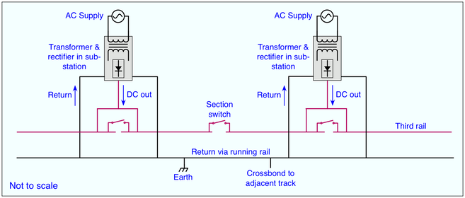
Figure 6: Diagram showing a 3rd rail DC power supply system and how current rail gaps are provided where the substations feed the line. Normally, each track is fed in each direction towards the next substation. This allows for some over supply and provides for continuity if one substation fails. The gaps are usually marked by a sign or a light which indicates if the current is on in the section ahead. Since the current may have been switched off to stop an arc or because of a short circuit, it is important that the train does not connect the dead section to the live section by passing over the gap and allowing its busline to bridge the gap. Modern systems link the traction current status to the signalling so that a train will not be allowed to proceed onto a dead section. Diagram: Author.
At various points along the line, there will be places where trains can be temporarily isolated electrically from the supply system. At such places, like terminal stations, "section switches" are provided. When opened, they prevent part of the line for being fed by the substation. They are used when it is necessary to isolate a train with an electrical fault in its current collection system.
Although 3rd rail is considered a suburban or metro railway system, 750 volt DC third rail supply has been used extensively over southern England and trains using it run regularly up to 145 km/h. This is about its limit for speed and has only spread over such a large area for historical reasons.
Return
What about the electrical return? There has to be a complete circuit, from the source of the energy out to the consuming item (light bulb, cooking stove or train) and back to the source, so a return conductor is needed for our railway. Simple – use the steel rails the wheels run on. Provided precautions are taken to prevent the voltage getting too high above the zero of the ground, it works very well and has done so for the last century. Of course, as many railways use the running rails for signalling circuits as well, special precautions have to be taken to protect them from interference.
The power circuit on the train is completed by connecting the return to brushes rubbing on the axle ends. The wheels, being steel, take it to the running rails. These are wired into the substation supplying the power and that does the job. The same technique is used for DC or AC overhead line supplies.
AC or DC traction
It doesn’t really matter whether you have AC or DC motors, nowadays either can work with an AC or DC supply. You just need to put the right sort of control system between the supply and the motor and it will work. However, the choice of AC or DC power transmission system along the line is important. Generally, it’s a question of what sort of railway you have. It can be summarised simply as AC for long distance and DC for short distance. Of course there are exceptions and we will see some of them later.
It is easier to boost the voltage of AC than that of DC, so it is easier to send more power over transmission lines with AC. This is why national electrical supplies are distributed at up to 765,000 volts AC . As AC is easier to transmit over long distances, it is an ideal medium for electric railways. Only the problems of converting it on the train to run DC motors restricted its widespread adoption until the 1960s.
DC, on the other hand was the preferred option for shorter lines, urban systems and tramways. However, it was also used on a number of main line railway systems, and still is in some parts of continental Europe, for example. Apart from only requiring a simple control system for the motors, the smaller size of urban operations meant that trains were usually lighter and needed less power. Of course, it needed a heavier transmission medium, a third rail or a thick wire, to carry the power and it lost a fair amount of voltage as the distance between supply connections increased. This was overcome by placing substations at close intervals – every three or four kilometres at first, nowadays two or three on a 750 volt system – compared with every 20 kilometres or so for a 25 kV AC line.
It should be mentioned at this point that corrosion is always a factor to be considered in electric supply systems, particularly DC systems. The tendency of return currents to wander away from the running rails into the ground can set up electrolysis with water pipes and similar metallics. This was well understood in the late 19th Century and was one of the reasons why London’s Underground railways adopted a fully insulated DC system with a separate negative return rail as well as a positive rail - the four-rail system. Nevertheless, some embarrassing incidents in Asia with disintegrating manhole covers near a metro line as recently as the early 1980s means that the problem still exists and isn’t always properly understood. Careful preparation of earthing protection in structures and tunnels is an essential part of the railway design process and is neglected at one’s peril.
Overhead Line (Catenary)
The mechanics of power supply wiring is not as simple as it looks (Figure 1). Hanging a wire over the track, providing it with current and running trains under it is not that easy if it is to do the job properly and last long enough to justify the expense of installing it. The wire must be able to carry the current (several thousand amps), remain in line with the route, withstand wind (in Hong Kong typhoon winds can reach 200 km/h), extreme cold and heat and other hostile weather conditions.
Overhead catenary systems, called "catenary" from the curve formed by the supporting cable, have a complex geometry, nowadays usually designed by computer. The contact wire has to be held in tension horizontally and pulled laterally to negotiate curves in the track. The contact wire tension will be in the region of 2 tonnes. The wire length is usually between 1000 and 1500 metres long, depending on the temperature ranges. The wire is zigzagged relative to the centre line of the track to even the wear on the train's pantograph as it runs underneath.
The contact wire is grooved to allow a clip to be fixed on the top side (Figure 7). The clip is used to attach the dropper wire. The tension of the wire is maintained by weights suspended at each end of its length. Each length is overlapped by its neighbour to ensure a smooth passage for the "pan". Incorrect tension, combined with the wrong speed of a train, will cause the pantograph head to start bouncing. An electric arc occurs with each bounce and a pan and wire will soon both become worn through under such conditions.

Figure 7: Overhead contact wire showing the grooves added to provide for the dropper clips. Photo: Coptech.
More than one pantograph on a train can cause a similar problem when the leading pantograph head sets up a wave in the wire and the rear head can’t stay in contact. High speeds worsen the problem. The French TGV (High Speed Train) formation has a power car at each end of the train but only runs with one pantograph raised under the high speed 25 kV AC lines. The rear car is supplied through a 25 kV cable running the length of the train. This would be prohibited in Britain due to the inflexible safety approach there.
A waving wire will cause another problem. It can cause the dropper wires, from which the contact wire is hung, to "kink" and form little loops. The contact wire then becomes too high and aggravates the poor contact.
AC Sections
Overhead lines are normally fed in sections like 3rd rail systems, but AC overhead sections are usually much longer. Each subsection is isolated from its neighbour by a section insulator in the overhead contact as shown in this picture below. The subsections can be joined through special high speed section switches.

Figure 8: Insulated neutral section in an overhead line. Photo: Author.
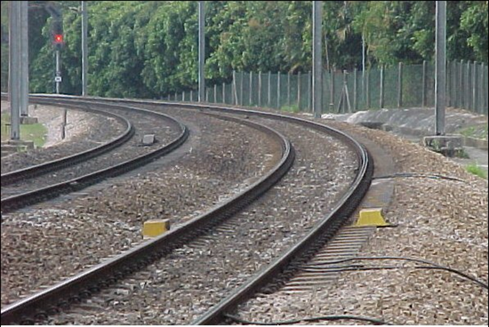
Figure 9: To reduce the arcing at a neutral section in the overhead catenary, some systems use track magnets to automatically switch off the power on the train on the approach to the neutral section. A second set of magnets restores the power immediately after the neutral section has been passed.
Catenary Suspension Systems
Various forms of catenary suspension are used depending on the system, its age, its location and the speed of trains using it. Broadly speaking, the higher speeds, the more complex the "stitching", although a simple catenary will usually suffice if the support posts are close enough together on a high speed route. Modern installations often use the simple catenary, slightly sagged to provide a good contact. It has been found to perform well at speeds up to 125 m/hr (200 km/hr).
At the other end of the scale, a tram depot may have just a single wire hung directly from insulated supports. As a pantograph passes along it, the wire can be seen to rise and fall. This is all that is necessary in a slow speed depot environment. I haven’t yet mentioned trolley poles as a method of current collection. These were used for current collection on low speed overhead systems and were common on trams or streetcars but they are now obsolete.

Figure 10: Overhead line suspension system. The weights and pulley system is designed to maintain contact wire tension. Photo: Author.
DC overhead wires are usually thicker and, in extreme load cases, double wires are used, as in Hong Kong Mass Transit’s 1500 v DC supply system. Up to 3000 volts overhead is used by DC main line systems (e.g., parts of France, Belgium and Italy) but below 1500 volts, a third rail can be used. In operating terms, the third rail is awkward because of the greater risk of it being touched at ground level. It also means that, if trains are stopped and have to be evacuated, the current has to be turned off before passengers can be allowed to wander the track. Third rail routes need special protection to be completely safe. On the other hand, some people consider the overhead catenary system a visual intrusion. Singapore, for example, has banned its use outside of tunnels.
Booster Transformers
On lines equipped with AC overhead wires, special precautions are taken to reduce interference in communications cables. If a communications cable is laid alongside rails carrying the return current of the overhead line supply, it can have unequal voltages induced in it. Over long distances the unequal voltages can represent a safety hazard. To overcome this problem, many systems used booster transformers. These are positioned on masts at intervals along the route. They are connected to the feeder station by a return conductor cable hung from the masts so that it is roughly the same distance from the track as the overhead line. The return conductor is connected to the running rail at intervals to parallel the return cable and rails. The effect of this arrangement is to reduce the noise levels in the communications cable and ensure the voltages remain at a safe level.

Figure 11: A schematic showing the arrangements for 25kV AC electrification systems using booster transformers (upper drawing) and the auto transformer system (lower drawing). The auto transformer system allows substations to be further apart without voltage drop. Drawing: Author.
Auto Transformers
A more efficient system of AC electrification is known as the auto transformer system. In effect, it is based on distributing power at 50 kV AC but feeding the power to the trains at 25 kV AC. To achieve this, the supply sub-station transformer is provided with a centre tap secondary winding at 50 kV (set to 55 kV for the maximum limit of contact wire voltage of 27.5 kV). The centre tap is solidly connected to ground so that one terminal is at +25 kV and another at -25 kV. The two supplies at a phase difference of 180 degrees.
With this system, the contact wire is fed at +25 kV and the feeder wire at -25 kV thus the voltage in between these circuits is 50 kV but to ground is 25 kV. The insulation and clearances may still be designed for 25 kV AC only.
Pantographs
Current is collected from overhead lines by pantographs. Pantographs are easy in terms of isolation - you just lower the pan to lose the power supply to the vehicle. However, they do provide some complications in other ways.
Since the pantograph is usually the single point power contact for the locomotive or power car, it must maintain good contact under all running conditions. The higher the speed, the more difficult the maintenance of good contact. We have already mentioned the problem (above) of a wave being formed in the wire by a pantograph moving at high speed.
Pantograph contact is maintained either by spring or air pressure. Compressed air pressure is preferred for high speed operation. The pantograph is connected to a piston in a cylinder and air pressure in the cylinder maintains the pantograph in the raised condition.
Originally, pantographs were just that, a diamond-shaped "pantograph" with the contact head at the top. Two contact faces are normally provided. More modern systems use a single arm pantograph - really just half of the original shape - a neater looking design (photo above).
The contact strips of the pantograph are supported by a lightweight transverse frame which has "horns" at each end. These are turned downwards to reduce the risk of the pantograph being hooked over the top of the contact wire as the train moves along. This is one of the most common causes of wires "being down". A train moving at speed with its pantograph hooked over the wire can bring down several kilometres of line before it is detected and the train stopped (Figure 12). The most sophisticated pantographs have horns which are designed to break off when struck hard, for example, by a dropper or catenary support arm. These special horns have a small air pressure tube attached which, if the pressure is lost, will cause the pan to lower automatically and so reduce the possible wire damage.
Figure 12: Russian video of a pantograph being damaged by an overhead wire out of position. Video is 30s long.
Multi-Voltage
Some train services operate over lines using more than one type of current. In cities such as London, New York City and Boston, the same trains run under overhead wires for part of the journey and use third rail for the remainder. In Europe, some locomotives are equipped to operate under four voltages - 25 kV AC, 15 kV AC, 3,000 V DC and 1,500 V DC. Modern electronics makes this possible with relative ease and cross voltage travel is now possible without changing locomotives.