Introduction
More Information
Train Brakes pages on this site.
Vacuum Brake description from the Railcar website.
North American Freight Train Brakes
The Westinghouse Air Brake a 19th century description from the Catskill Archive
Electric motors are a common means of powering a train, whether the energy required is carried on-board the train in the form of a diesel engine and its fuel or obtained from outside the train by connection with an external power supply carried by an overhead line or third rail. Electric traction is widely used around the world, particularly for routes with dense traffic, like urban and suburban railways or long distance, high speed lines that need electric traction to obtain the speeds required for inter-city travel. There are a number of different systems of electric traction and these are described here.
The DC Traction Motor
Historically, the DC motor was the mainstay of electric traction drives on both electric and diesel-electric rolling stock. Many examples are still in use around the world. The motor consists of two parts, a rotating armature and a fixed field (Figure 1). The fixed field consists of tightly wound coils of wire fitted inside the motor case. The armature is another set of coils wound round a central shaft. It is connected to the field through "brushes" which are spring loaded contacts pressing against an extension of the armature called the commutator. The commutator collects all the terminations of the armature coils and distributes them in a circular pattern to allow the correct sequence of current flow.

Figure 1: Schematic of the basic structure of a series wound DC traction motorshowing the main parts and hoew the rotor (the armature) sits inside the field coils (the stator). The two parts are joined electrically through the commutator. The commutator rotates with the armature and provides the connection to the field coils through brushes. Diagram: Author.
The
DC motor works because, simply put, when a current is passed through
the motor circuit, there is a reaction between the current in the field
and the current in the armature which causes the armature to turn. The
armature and the field are connected in series and the whole motor is
referred to as "series wound".
A series wound DC motor has a low
resistance field and armature circuit. Because of this, when voltage is
applied to it, the current is high (Ohms Law: current =
voltage/resistance). The advantage of high current is that the magnetic
fields inside the motor are strong, producing high torque (turning
force), so it is ideal for starting a heavy object like a train. The
disadvantage is that the current flowing into the motor has to be
limited somehow, otherwise the supply could be overloaded and/or the
motor and its cabling could be damaged. At best, the torque would exceed
the adhesion and the driving wheels would slip. Traditionally,
resistors were used to limit the initial current.
DC control circuit
As the DC motor starts to turn, the interaction of the magnetic fields inside it causes it to generate a voltage internally. This "back voltage" opposes the applied voltage and the current that flows is governed by the difference between the two. So, as the motor speeds up, the internally generated voltage rises, the effective voltage falls, less current is forced through the motor and thus the torque falls. The motor naturally stops accelerating when the drag of the train matches the torque produced by the motors. To continue accelerating the train, resistors are switched out in steps, each step increasing the effective voltage and thus the current and torque for a little bit longer until the motor catches up. This can be heard and felt in older DC trains as a series of clunks under the floor, each accompanied by a jerk of acceleration as the torque suddenly increases in response to the new surge of current. When no resistor is left in the circuit, the full line voltage is applied directly to the motor. The train's speed remains constant at the point where the torque of the motor, governed by the effective voltage, equals the drag - sometimes referred to as balancing speed. If the train starts to climb a grade, the speed reduces because drag is greater than torque. But the reduction in speed causes the back voltage to decline and thus the effective voltage rises - until the current forced through the motor produces enough torque to match the new drag.
Figure 2: Schematic of a simple traction motor power control circuit. Most DC motor circuits are arranged to control two or four motors. The control range is enhanced by changing the connections to the motors as the train accelerates. The system is known as "series-parallel control”. The diagram shows the resistors and contactors used to regulate the voltage across the motors. The resistance is cut out in steps normally in the sequence shown for both series and parallel connections. Diagram: Author.
On an electric train, the driver originally had to control the cutting out of resistance manually but, by the beginning of the First World War in 1914, automatic acceleration was being used on multiple-unit trains. This was achieved by an accelerating relay (often called a "notching relay") in the motor circuit which monitored the fall of current as each step of resistance was cut out. All the driver had to do was select low, medium or full speed (called "shunt", "series" and "parallel" from the way the motors were connected in the resistance circuit) and the equipment would do the rest.
Motor Control and Protection

Figure 3: Schematic showing a DC traction motor control circuit with notching, overload and no-volt relays. Diagram: Author.
As
described above, DC motors are controlled by a "notching relay" set
into the power circuit (Figure 3). But there are other relays provided
for motor protection. Sharp spikes of current will quickly damage a DC
motor so protective equipment is provided in the form of an "overload
relay", which detects excessive current in the circuit and, when it
occurs, switches off the power to avoid damage to the motors. Power is
switched off by means of Line Breakers, one or two heavy-duty switches
similar to circuit breakers which are remotely controlled. They would
normally be opened or closed by the action of the driver's controller
but they can also be opened automatically by the action of the overload
relay.
A further protective device is also provided in the
classic DC motor control circuit. This is the "no-volt" relay, which
detects power lost for any reason and makes sure that the control
sequence is returned to the starting point (i.e. all the resistances are
restored to the power circuit) before power could be re-applied. This
is necessary to ensure that too much current is not applied to a motor
which lost speed while current was off.
AC and DC Motors
Both AC (Alternating Current) and DC motors have the same basic structure but there are differences and, for various reasons, the DC motor was originally the preferred form of motor for railway applications and most systems used it. Nowadays, modern power electronics has allowed the use of AC motors and, for most new equipments built today, the AC motor is the type used.
Often, people ask about the differences between AC and DC motors as used in locomotives and multiple-units. In the early days of electric traction at the beginning of this century both types were tried. The limits of the technology at the time favoured the DC motor. It provided the right torque characteristic for railway operation and was reasonably simple to control.
By the early 1980s, power electronics had progressed to the stage where the 3-phase AC motor had become a serious and more efficient alternative to the DC motor because:
1. They are simpler to construct, they require no mechanical contacts to work (such as brushes) and they are lighter than DC motors for equivalent power.
2. Modern electronics allow AC motors to be controlled effectively to improve both adhesion and traction.
3. AC motors can be microprocessor controlled to a fine degree and can regenerate current down to almost a stop whereas DC regeneration fades quickly at low speeds.
4. They are more robust and easier to maintain than DC motors.
This type of motor is commonly called the Asynchronous Motor and was often referred to as the squirrel cage motor on account of its early design form. Both AC and DC motors are similar to look at externally but there are differences in construction, particularly because the DC motor has a commutator and brushes which the AC motor does not.
Nose Suspended Motor
In electric trains or locomotives, the DC motor was traditionally mounted in the bogie frame supported partially by the axle which it drove and partially by the bogie frame. The motor case was provided with a "nose" which rested on a bracket fixed to the transom of the bogie. It was called a "nose suspended motor" (see the Bogies page for a diagram) and is still common around the world. Its main disadvantage is that part of the weight rests on the axle and is therefore unsprung. This leads to greater wear on bogie and track. Nowadays, designers try to ensure all the motor weight is sprung by ensuring it is carried entirely by the bogie frame - a frame mounted motor.
Quill Drive
A quill is described in the dictionary as, "the hollow stem of a feather" and "a bobbin or spindle", as well as a "feather" and, alternatively, what a porcupine has on its back. In railway traction terms, a quill drive is where a hollow shaft is placed round the driving axle and the motor drives the quill rather than driving the axle as it does with a nose suspended drive. The quill itself is attached, at one end, to one of the wheels by means of rubber bushed links and, at the other end, to the gearwheel by similar links. The big advantage of such drives is that all the weight of the motor is carried in the bogie frame (so it is a frame mounted motor) instead of it being directly supported by the axle and therefore partially unsprung.

Figure
4: An example of a traction motor with quill drive. Various forms of
quill drive have been used over the years. Older versions used radially
mounted coil steel springs instead of rubber to connect the links to
the wheels. Some, like the example shown here, have the motor mounted
parallel with the axle. Others have the motor at a right angle to the
axle, as in the the UK Class 91 electric locomotives.
In German the quill is called "Hohlwelle" (hollow shaft) and used in the ICE1 and ICE2 as well as the electric locomotive Class 101. (Source Tobias Benjamin Koehler 19 Oct 98).
Monomotor Bogie
As its name implies, the monomotor bogie has a single motor which drives both axles. The design is much favoured by French engineering, where it was introduced in the 1950s for the rubber tyred train concept. The motor is mounted longitudinally in the centre of the bogie and drives each axle through a differential gearbox, similar to a road vehicle. The differential gears are required to compensate for the operation of the rubber tyres round curves. It requires a special bogie frame construction to accommodate the motor.
To
accommodate a rubber tyred train, the standard railway track has to
have concrete strips laid on the outside of the conventional rails and
additional vertical steel guide rails on the outside of those. The steel
guide rails act as positive and negative traction current rails.

Figure 5: Monomotor bogie as used on the Lyon Metro. The vehicles normally rest of the rubber tyres but the railway wheels are required for guidance throughturnouts and in case a tyre becomes deflated. The system is expensive to install and difficult to maintain.
Linear Motor
Another
form of traction used on some urban railways is the linear motor. The
principal, compared with a standard motor, is shown here. This simple
diagram shows the principal of the linear motor. The conventional DC motor
consists of a fixed part (the stator) and a moving part (the rotor).
Both parts are contained in a case on the train and the rotor is
connected to the axle by a pinion/gear arrangement. When the armature
turns, the wheel turns.
For
the linear motor, the two parts are separated with one placed on the
train and the other on the track. Both parts are unwrapped and they
are swapped so that the fixed part of the DC motor becomes the moving
part of the linear motor mounted on the train while the former moving
part of the DC motor is fixed to the track. The electro-magnetic
interaction between the current in the fixed part and that in the moving
part causes the train to be drawn along the line. There is a very small
air gap (about 10 mm) between the two parts as shown in this photo.
The efficiency of the linear motor is about 60% of the conventional motor but it has the advantage of less moving parts and it does not have the reliance on adhesion of the conventional motor.
Multiple Unit Control
Originally derived from lift operation over a hundred years ago, multiple unit (MU) control has become the most common form of train control in use around the world today.
Electric locomotives were originally designed so that the motors were controlled directly by the driver. The traction power circuits passed through a large controller mounted in the driving cab. A handle was rotated by the driver as necessary to change the switches in the circuit to increase or reduce power as required. This arrangement meant that the driver had to remain close to the motors if long and heavy, power-carrying cables were to be avoided.
While this arrangement worked well enough, the desire to get rapid turnrounds on city streetcar railways led to the adoption of remote control. The idea was that, if the motors could be remotely controlled, a set of driver's controls could be placed at each end of the train. It would not be necessary to have a locomotive added at the rear of an arriving train to allow it to make the return journey. A cab would be installed at each end of the train and the driver just had to change ends to change direction. Once this idea was established, it was realised that the motors could be placed anywhere along the train, with as many or as few as required to provide the performance desired. With this development, more but smaller motors were scattered along the train instead of building a few large motors in a locomotive. This is how the concept of motor cars and trailer cars evolved. Trailer cars are just passenger carrying vehicles but motor cars are passenger carrying vehicles which have motors and their associated control equipment.
Multiple unit trains, as these trains became known, were equipped with control cables called train lines, which connected the driver's controls with the motor controls and power switches on each motor car. The opening and closing of the power switches was achieved by electro-magnetic relays, using principles originally designed for lifts. While the idea was being established on passenger trains, it was also adopted on locomotives. It quickly became the standard method of control.
The Relay
A relay is really a remotely controlled switch. In Figure 6, a power circuit contains a switch which is opened and closed by operation of a relay. The relay is activated by a magnetic core which is energised when a controlling switch is closed. As the core is energised, it lifts and closes a pair of contacts in a second circuit - usually a power circuit. The current required for the relay is usually much lower than that used for the power circuit so it can be provided by a battery.
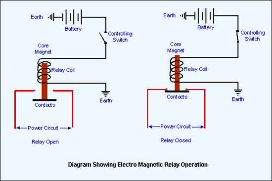
Figure 6: A pair of schematics of a relay showing that, if the controlling switch is open, the relay is de-energised and the power circuit contacts are open. If
the controlling switch is closed, as in the right hand diagram, the
relay is therefore energised and its core magnet lifts to close the
contacts in the power circuit.
Applied to a simple lift operating between two levels, a control switch on each landing could use relays to switch on the lift motor to move the lift up or down. On a train, the controlling switch could be located anywhere on the train to activate the relays controlling the power to the motors. The same principles can be used to carry out any other switching e.g. for lights or heating. It represents a safe and simple way of transmitting commands to a number of equipments in a train and it is the foundation upon which multiple unit control was based. On modern rolling stock, the relay is being replaced in many applications by electronic control, which speeds operation, eliminates the mechanical movements required and allows the miniaturisation of control systems.
The Contactor
As we have seen from the description above, the relay must have a current applied to it all the time it is required to be closed. To avoid having current on to, say, a lighting control relay all the time, a different type of remotely controlled switch is used. This is called a contactor.
The contactor is really a latched relay. It can also be called (in the US) a "momentary switch". It only requires current to be on for a "moment" for it to operate. In order to keep the contacts closed once the control current is lost, the power circuit contacts are held in position by a mechanical latch. When it is necessary to open the power circuit, the latch is released and the contacts drop open.

Figure 7: A schematic showing how a contactor is operated by two coils, each with their own controlling switch. In this case, the contactor is closed or "set" by pressing the ON button and opened, or "tripped" by pressing the OFF button. Both ON and OFF buttons are sprung so that only a momentary current is used to activate the coil.
Contactors are widely used on trains and, for us, are a good example to demonstrate how multiple unit control works in practice.
Multiple Unit Control
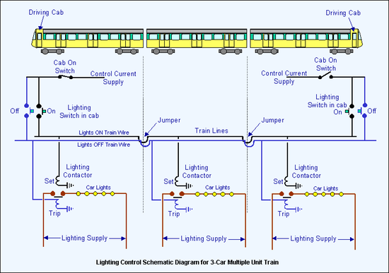
Figure 8: This diagram illustrates the principal of multiple unit (MU) control as applied to a 3-car train. This is a simple example showing how the lighting on each car is switched on and off by a lighting contactor. The contactor is latched closed when its "set" coil is energised or opened by the "trip" coil to unlatch it when required to switch off the lighting.
In a multiple unit system, sets of equipment along the train are controlled from one location. In Figure 8, all the lighting
contactors on the train are connected to train wires, in this case one
for “lights on” (in black) and one for “lights off” (in blue). The ON
and OFF buttons are in the driving cabs at each end of the train so, the
lighting can be switched on or off from either end of the train.
To
prevent unauthorised use of the control buttons, most of the important
circuits in the cab are isolated by a "control switch" or "cab on
switch". This is key operated and keys are only issued to qualified
drivers or maintainers. It also means that, in our example, lights can
only be switched on or off from one end at a time. The same principle,
using contactors or relays, is applied to all other systems on the train
- driving controls, braking control, heaters, doors, air conditioning,
public address etc.
Of course, current for the equipment on each vehicle, as in this case, lighting, comes from a separate source - the auxiliary supplies - in the form of a battery, an alternator, an inverter or a power train line.
Forward and Reverse
How, one might ask, does one ensure that a number of locomotives or EMUs (or DMUs for that matter), coupled together to work in multiple, perhaps facing in different directions, will all respond to the driver's command to go in the same direction, say forward, from the cab where he is sitting? How do you prevent one locomotive taking off in the wrong direction? Well, it's built in to the wiring and it's simple, as shown in Figure 9.

Figure 9: A diagram showing the wiring schematic required to allow locomotives or multiple units working in the same train to operate in forward and reverse regardless of the direction of the driving positions.
Each power unit (whether it be a locomotive or
EMU) has a forward wire and a reverse wire connected to a "Forward and
Reverse" switch of one sort or another in the cab. Looking at Unit 1,
if the driver selects "Forward", the forward wire (in red) is energised
and the "forward relay" (the arrow shows the direction of movement
obtained for each relay) is energised to make the locomotive move in the
forward direction.
To ensure the correct direction is achieved
by a second locomotive (Unit 2) that is coupled to the first, the
forward and reverse wires are crossed over in the jumper cable. If the
second locomotive faces in the opposite direction to the first, its
reverse wire (shown in black here) will be energised to make the loco
run in the same direction as its partner. To make sure this always
happens, all multiple unit control jumpers have their forward and
reverse wires crossed.
But, you might ask, what if the locos
both face in the same direction? You don't need the crossed wires in
the jumper. The crossed wires in the jumper will make the second loco
go the opposite way. No, that's been solved too. So that the same
jumper with the crossed wires can be used anywhere, the forward and
reverse wires are also crossed ON each locomotive, only at one end,
usually near the jumper socket. Now, no matter which way round the
locos are coupled to each other, and in what order, the forward command
will always make all units drive in the same direction and the reverse
command will make all units drive in the opposite direction.
One
final point. The jumper heads are designed so that they can only be
inserted one way into the coupler socket on the locomotive, rather like a
USB plug on a computer.
Modern Control Systems
Modern systems use single wires or even fibre optic cables for controls. The system is sometimes referred to as "multiplexing", where a number of control signals are sent along a single wire. Some administrations require hard wired controls for safety systems like train braking but diverse programming can be used to make this redundant.
Series-Parallel Control
Although series-parallel connecting was common for resistance controlled DC traction motor control, it has been replaced for new equipment by electronic control. However, there are many series-parallel systems still in use around the world. See Figure 2 above.
Field Weakening
The
DC motor can be made to run faster than the basic "balancing speed"
achieved whilst in the full parallel configuration without any
resistance in circuit. This is done by "field shunting". An additional
circuit is provided in the motor field to weaken the current flowing
through the field. The weakening is achieved by placing a resistance in
parallel with the field. This has the effect of forcing the armature
to speed up to restore the balance between its magnetic filed and that
being produced in the field coils. It makes the train go faster.
Various
stages of field weakening can be employed, according to the design of
the motor and the intended purpose. Some locomotives used as many as
six steps of field weakening.
Regenerative Braking
Since the DC motor and a DC generator are virtually the same machine mechanically, it was immediately realised that a train could use its motors to act as generators and that this would provide some braking effect if a suitable way could be found to dispose of the energy. The idea formed that if the power could be returned to the source, other trains could use it. Trains were designed therefore, which could return current, generated during braking, to the supply system for use by other trains. Various schemes were tried over many years with more or less success but it was not until the adoption of modern electronics that reliable schemes have been available.
Rheostatic Braking
The major drawback with the regenerative braking system is that the line is not always able to accept the regenerated current. Some railways had substations fitted with giant resistors to absorb regenerated current not used by trains but this was a complex and not always reliable solution. As each train already had resistors, it was a logical step to use these to dispose of the generated current. The result was rheostatic braking. When the driver calls for brake, the power circuit connections to the motors are changed from their power configuration to a brake configuration and the resistors inserted into the motor circuit. As the motor generated energy is dispersed in the resistors and the train speed slows, the resistors are switched out in steps, just as they are during acceleration. Rheostatic braking on a DC motored train can be continued down to less than 20 mph when the friction brakes are used to bring the train to a stop.
Before the advent of power electronics, there were some attempts to combine the two forms of what we now call "dynamic braking" so that the generated current would go to the power supply overhead line or third rail if it could be absorbed by other trains but diverted to on-board resistors if not.
In the case of diesel-electric locomotives, dynamic braking is restricted to the rheostatic type. Racks of resistors can often be seen on the roofs of heavy-haul locomotives for which dynamic braking is a big advantage on long downhill grades where speed must be maintained at a restricted level for long periods.
AC and DC Differences
To understand the principles of modern traction power control systems, it is worth a look at the basics of DC and AC circuitry. DC is direct current - it travels in one direction only along a conductor. AC is alternating current - so called because it changes direction, flowing first one way along the conductor, then the other. It does this very rapidly. The number of times it changes direction per second is called the frequency and is measured in Hertz (Hz). It used to be called cycles per second, in case you've read of this in historical papers. In a diagrammatic representation, the two types of current appear as shown in the diagram above left.
From a transmission point of view, AC is better than DC because it can be distributed at high voltages over a small size conductor wire, whereas DC needs a large, heavy wire or, on many DC railways, an extra rail. DC also needs more frequent feeder substations than AC - the ratio for a railway averages at about 8 to 1. It varies widely from one application to another but this gives a rough idea. See also Electric Traction Pages Power Supplies.
Over the hundred years or so since the introduction of electric traction on railways, the rule has generally been that AC is used for longer distances and main lines and DC for shorter, suburban or metro lines. DC gets up to 3000 volts, while AC uses 15,000 - 50,000 volts.
Until recently, DC motors have been the preferred type for railways because their characteristics were just right for the job. They were easy to control too. For this reason, even trains powered from AC supplies were usually equipped with DC motors.
AC Locomotives with DC Drives
This diagram (above) shows a simplified schematic for a 25 kV AC electric locomotive used in the UK from the late 1960s. The 25 kV AC is collected by the pantograph and passed to the transformer. The transformer is needed to step down the voltage to a level which can be managed by the traction motors. The level of current applied to the motors is controlled by a "tap changer", which switches in more sections of the transformer to increase the voltage passing through to the motors. It works in the same way as the resistance controllers used in DC traction, where the resistance contactors are controlled by a camshaft operating under the driver's commands.
Before being passed to the motors, the AC has to be changed to DC by passing it through a rectifier. For the last 30 years, rectifiers have used diodes and their derivatives, the continuing development of which has led to the present, state-of-the-art AC traction systems.
The Diode
A diode is a device with no moving parts, known as a semi-conductor, which allows current to flow through it in one direction only. It will block any current which tries to flow in the opposite direction. Four diodes arranged in a bridge configuration, as shown below, use this property to convert AC into DC or to "rectify" it. It is called a "bridge rectifier". Diodes quickly became popular for railway applications because they represent a low maintenance option. They first appeared in the late 1960s when diode rectifiers were introduced on 25 kV AC electric locomotives.
The Thyristor
The thyristor is a development of the diode. It acts like a diode in that it allows current to flow in only one direction but differs from the diode in that it will only permit the current to flow after it has been switched on or "gated". Once it has been gated and the current is flowing, the only way it can be turned off is to send current in the opposite direction. This cancels the original gating command. It's simple to achieve on an AC locomotive because the current switches its direction during each cycle. With this development, controllable rectifiers became possible and tap changers quickly became history. A thyristor controlled version of the 25 kV AC electric locomotive traction system looks like the diagram here on the left.
A tapping is taken off the transformer for each DC motor and each has its own controlling thyristors and diodes. The AC from the transformer is rectified to DC by chopping the cycles, so to speak, so that they appear in the raw as half cycles of AC as shown on the left.
In reality, a smoothing circuit is added to remove most of the "ripple" and provide a more constant power flow as shown in the diagram (left). Meanwhile, the power level for the motor is controlled by varying the point in each rectified cycle at which the thyristors are fired. The later in the cycle the thyristor is gated, the lower the current available to the motor. As the gating is advanced, so the amount of current increases until the thyristors are "on" for the full cycle. This form of control is known as "phase angle control".
SEPEX
In more recent thyristor control systems, the motors themselves are wired differently from the old standard DC arrangement. The armatures and fields are no longer wired in series, they are wired separately - separate excitement, or SEPEX. Each field has its own thyristor, which is used to control the individual fields more precisely.
Since the motors are separately excited, the acceleration sequence is carried out in two stages. In the first stage, the armature is fed current by its thyristors until it reaches the full voltage. This might give about 25% of the locomotive's full speed. In the second stage, the field thyristors are used to weaken the field current, forcing the motor to speed up to compensate. This technique is known as field weakening and was already used in pre-electronic applications.
A big advantage of SEPEX is that wheel slip can be detected and corrected quickly, instead of the traditional method of either letting the wheels spin until the driver noticed or using a wheel slip relay to switch off the circuit and then restart it.
DC Choppers
The traditional resistance control of DC motors wastes current because it is drawn from the line (overhead or third rail) and only some is used to accelerate the train to 20-25 mph when, at last, full voltage is applied. The remainder is consumed in the resistances. Immediately thyristors were shown to work for AC traction, everyone began looking for a way to use them on DC systems. The problem was how to switch the thyristor off once it had been fired, in other words, how to get the reverse voltage to operate on an essentially one-way DC circuit. It is done by adding a "resonant circuit" using an inductor and a capacitor to force current to flow in the opposite direction to normal. This has the effect of switching off the thyristor, or "commutating" it. It is shown as part of the complete DC thyristor control circuit diagram (Figure 10). It has its own thyristor to switch it on when required.

Figure 10: Schematic of a DC thyristor traction control circuit.
Two other features of the DC thyristor circuit are the "freewheel diode" and the "line filter". The freewheel diode keeps current circulating through the motor while the thyristor is off, using the motor's own electro magnetic inductance. Without the diode circuit, the current build up for the motor would be slower.
Thyristor control can create a lot of electrical interference - with all that chopping, it's bound to. The "line filter" comprises a capacitor and an inductor and, as its name suggests, it is used to prevent interference from the train's power circuit getting into the supply system.
The thyristor in DC traction applications controls the current applied to the motor by chopping it into segments, small ones at the beginning of the acceleration process, gradually enlarging as speed increases. This chopping of the circuit gave rise to the nickname "chopper control". It is visually represented by the diagram below, where the "ON" time of the thyristor is regulated to control the average voltage in the motor circuit. If the "ON" time is increased, so does the average voltage and the motor speeds up. The system began to appear on UK EMUs during the 1980s.
Dynamic Braking
Trains equipped with thyristor control can readily use dynamic braking, where the motors become generators and feed the resulting current into an on-board resistance (rheostatic braking) or back into the supply system (regenerative braking). The circuits are reconfigured, usually by a "motor/brake switch" operated by a command from the driver, to allow the thyristors to control the current flow as the motors slow down. An advantage of the thyristor control circuitry is its ability to choose either regenerative or rheostatic braking simply by automatically detecting the state of receptivity of the line. So, when the regenerated voltage across the supply connection filter circuit reaches a preset upper limit, a thyristor fires to divert the current to the on-board resistor.
The GTO Thyristor
By the late 1980s, the thyristor had been developed to a stage where it could be turned off by a control circuit as well as turned on by one. This was the "gate turn off" or GTO thyristor. This meant that the thyristor commutating circuit could be eliminated for DC fed power circuits, a saving on several electronic devices for each circuit. Now thyristors could be turned on and off virtually at will and now a single thyristor could be used to control a DC motor.
It is at this point that the conventional DC motor reached its ultimate state in the railway traction industry. Most systems now being built use AC motors.
AC Motors
There are two types of AC motor, synchronous and asynchronous. The synchronous motor has its field coils mounted on the drive shaft and the armature coils in the housing, the inverse of normal practice. The synchronous motor has been used in electric traction - the most well-known application being by the French in their TGV Atlantique train. This used a 25 kV AC supply, rectified to DC and then inverted back to AC for supply to the motor. It was designed before the GTO thyristor had been sufficiently developed for railway use and it used simple thyristors. The advantage for the synchronous motor in this application is that the motor produces the reverse voltages needed to turn off the thyristors. It was a good solution is its day but it was quickly overtaken by the second type of AC motor - the asynchronous motor - when GTO thyristors became available.
The Asynchronous Motor
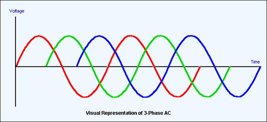
Figure 11: Schematic of 3-phase AC cycles
The asynchronous motor, also called the induction motor, is an AC motor which comprises a rotor and a stator like the DC motor, but the AC motor does not need current to flow through the armature. The current flowing in the field coils forces the rotor to turn. However, it does have to have a three phase supply, i.e. one where AC has three conductors, each conducting at a point one third into the normal cycle period, as visually represented in Figure 11.
The two big advantages of the 3-phase design are that, one, the motor has no brushes, since there is no electrical connection between the armature and the fields and, two, the armature can be made of steel laminations, instead of the large number of windings required in other motors. These features make it more robust and cheaper to build than a commutator motor.
AC Drive
Modern electronics has given us the AC drive. It has only become available with modern electronics because the speed of a 3-phase AC motor is determined by the frequency of its supply but, at the same time, the power has to be varied. The frequency used to be difficult to control and that is why, until the advent of modern electronics, AC motors were almost exclusively used in constant speed applications and were therefore unsuitable for railway operation. A modern railway 3-phase traction motor is controlled by feeding in three AC currents which interact to cause the machine to turn. The three phases are most easily provided by an inverter which supplies the three variable voltage, variable frequency (VVVF) motor inputs. The variations of the voltage and frequency are controlled electronically.

Figure 12: Schematic of 25kV traction control system with the 25kV fed into a transformer. A secondary winding is taken off for the AC to DC converter, which produces a DC output to pass to the motor converter, which then provides the controlled three phases to the traction motors.
The AC motor can be used by either an AC or DC traction supply system. In the case of AC supply (Figure 12), the line voltage (say 25kV single phase) is fed into a transformer and a secondary winding is taken off for the AC to DC converter (rectifier) which produces a DC output of say 1500 - 2000 volts depending on the application. This is then passed to the motor converter (inverter) which provides the controlled three phases to the traction motors. The connection between the rectifier and the inverter is called the DC link. This usually also supplies an output for the train's auxiliary circuits.
All the thyristors are GTOs, including those in the rectifier, since they are now used to provide a more efficient output than is possible with the older thyristors. In addition, all the facilities of DC motor control are available, including dynamic braking, but are provided more efficiently and with less moving parts. Applied to a DC traction supply, the 3-phase set-up is even more simple, since it doesn't need a transformer or a rectifier. The DC line voltage is applied to the inverter, which provides the 3-phase motor control.
Control of these systems is complex but it is all carried out by microprocessors. The control of the voltage pulses and the frequency has to be matched with the motor speed. The changes which occur during this process produce a set of characteristic buzzing noises which sound like the "gear changing" of a road vehicle and which can clearly be heard when riding on the motor car of an AC driven EMU.
IGBT
Having got AC drive using GTO thyristors universally accepted (well, almost) as the modern traction system to have, power electronics engineers then produced a new development. This is the IGBT or Insulated Gate Bipolar Transistor. The transistor was the forerunner of modern electronics, (remember transistor radios?) and it could be turned on or off like a thyristor but it doesn't need the high currents of the thyristor turn off. However it was, until very recently, only capable of handling very small currents measured in thousandths of amps. Now, the modern device, in the form of the IGBT, can handle thousands of amps and it has appeared in traction applications. A lower current version was first used instead of thyristors in auxiliary supply inverters in the early 1990s but a higher rated version has now entered service in the most recent AC traction drives. Its principle benefit is that it can switch a lot faster (three to four times faster) than GTOs. This reduces the current required and therefore the heat generated, giving smaller and lighter units. The faster switching also reduces the complex "gearing" of GTOs and makes for a much smoother and more even sounding acceleration buzz from under the train. With IGBTs, "gear changing" has gone.
Permanent Magnet Motor
The next development in electric motor design is the permanent magnet motor. This is a 3-phase AC synchronous motor with the usual squirrel cage construction replaced by magnets fixed in the rotor. The motor requires a complex control system but it can be up to 25% smaller than a conventional 3-phase motor for the same power rating. The design also gives lower operating temperatures so that rotor cooling isn't needed and the stator is a sealed unit with integral liquid cooling. By 2011, a number of different types of trains had been equipped with permanent magnet motors, including 25 AGV high speed train sets, trams in France and Prague and EMUs in Europe and Japan. The reduced size is particularly attractive for low floor vehicles where hub motors can be an effective way of providing traction in a compact bogie. Development of motor design and the associated control systems continues and it is certain that the permanent magnet motor will be seen on more railways in the future. A good description of the motor by Stuart Hillmansen, Felix Schmid and Thomas Schmid is in Railway Gazette International, February 2011.